Tools Required
| • | EN-48243
Engine Assembly Remove/Install Pallet |
| • |
EN-48244
Engine Assembly Remove/Install Pallet Supporter |
Removal Procedure
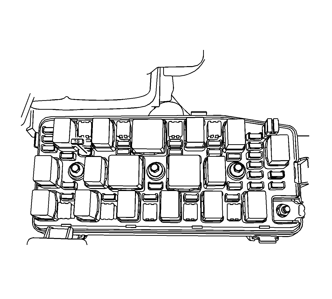
- Remove the fuel pump fuse.
- Start the engine. After it stalls, crank the engine for 10 seconds to rid the fuel system of fuel pressure.
- Drain the engine oil.
- Drain the engine coolant. Refer to
Cooling System Draining and Filling
.
- Drain the power steering oil.
- Drain the transaxle oil. Refer to
Transmission Fluid Replacement
for the AISIN or LE automatic transaxle or
Transmission Fluid Replacement
for the five-speed manual
transaxle.
- Discharge the air conditioning system, if equipped. Refer to
Refrigerant Recovery and Recharging
.
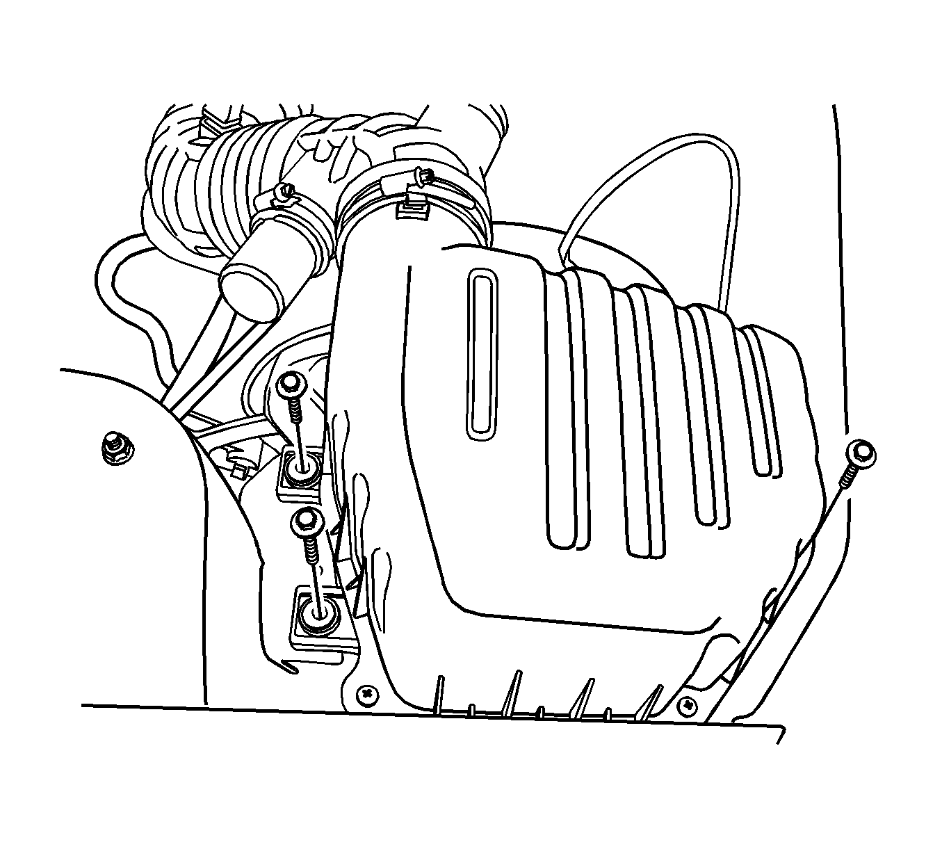
- Disconnect the intake air temperature (IAT) sensor connector.
- Remove the engine beautification cover.
- Disconnect the breather hose and PCV hose from the cylinder head cover.
- Remove the air cleaner assembly. Refer to
Air Cleaner Assembly Replacement
.
- Remove the resonator from the electronic throttle body.
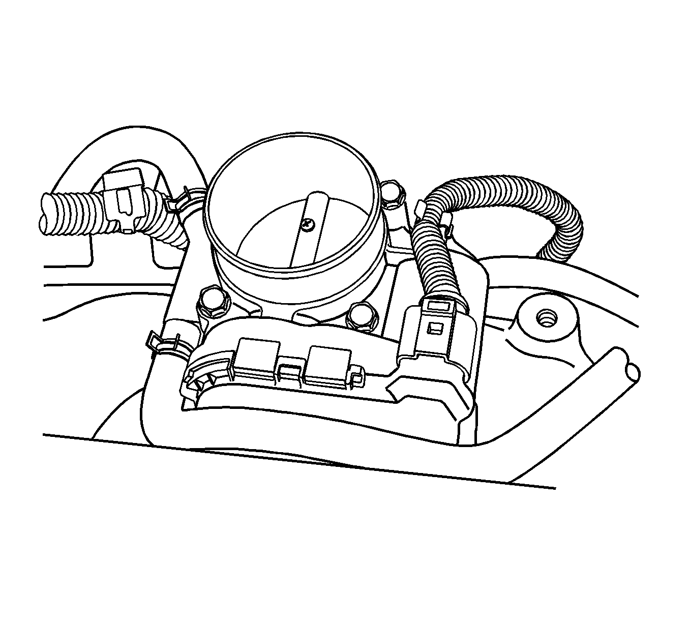
- Disconnect the upper radiator hose from the thermostat.
- Disconnect the lower radiator hose from the coolant pipe.
- Disconnect the coolant hoses from the electronic throttle body.
- Disconnect the surge tank hose from the cylinder block.
- Disconnect the heater outlet hose from the coolant pipe.
- Disconnect the heater inlet hose from the cylinder head.
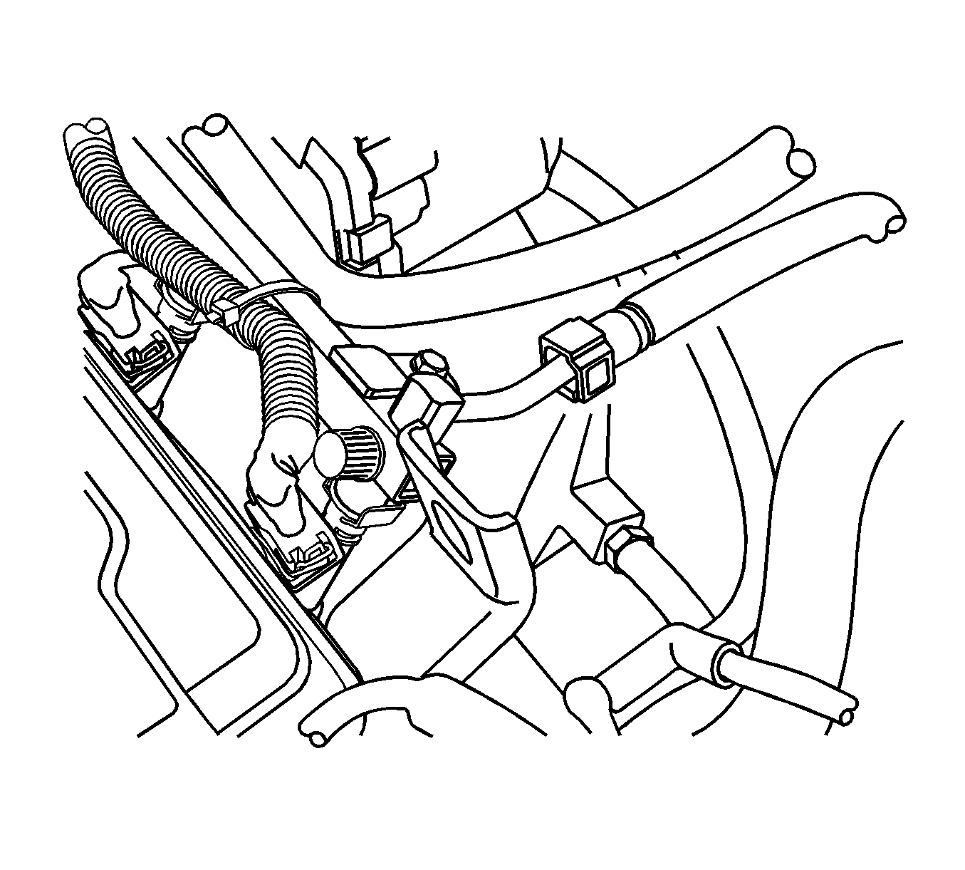
- Disconnect the fuel feed line from the fuel rail.
- Disconnect the power steering return hose and the pressure hose from the power steering pump. Refer to
Power Steering Return Hose Replacement
and
Power Steering Pressure Pipe/Hose Replacement
.
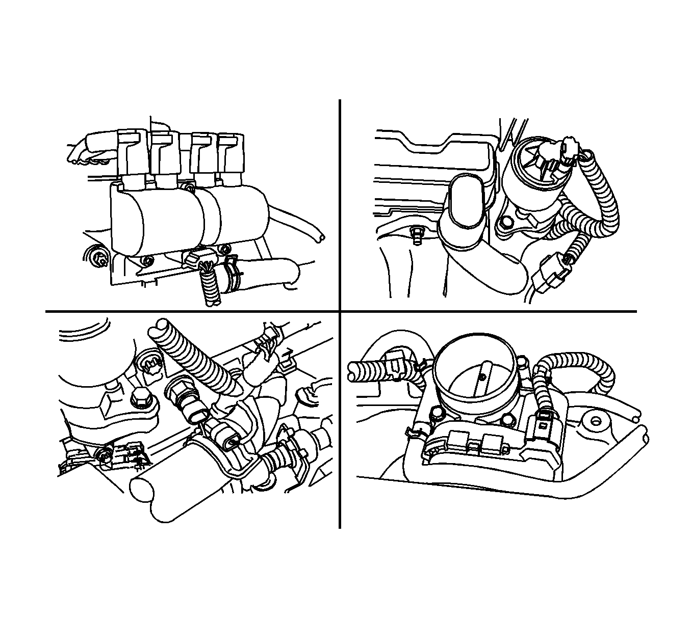
- Disconnect all of the necessary electrical connectors, such as the following:
| • | Exhaust gas recirculation valve |
| • | Coolant temperature sensor |
| • | Electronic throttle control system |
| • | Crankshaft position sensor |
| • | Camshaft position sensor |
| • | Manifold absolute pressure sensor |
| • | Alternator and starter terminal |
- Remove the ground terminals from the starter, intake manifold and cylinder block.
- Disconnect all of the necessary vacuum lines, including the brake booster vacuum hose.
- Remove the A/C compressor. Refer to
Air Conditioning Compressor Replacement
.
- Remove the engine electrical wires from the engine.
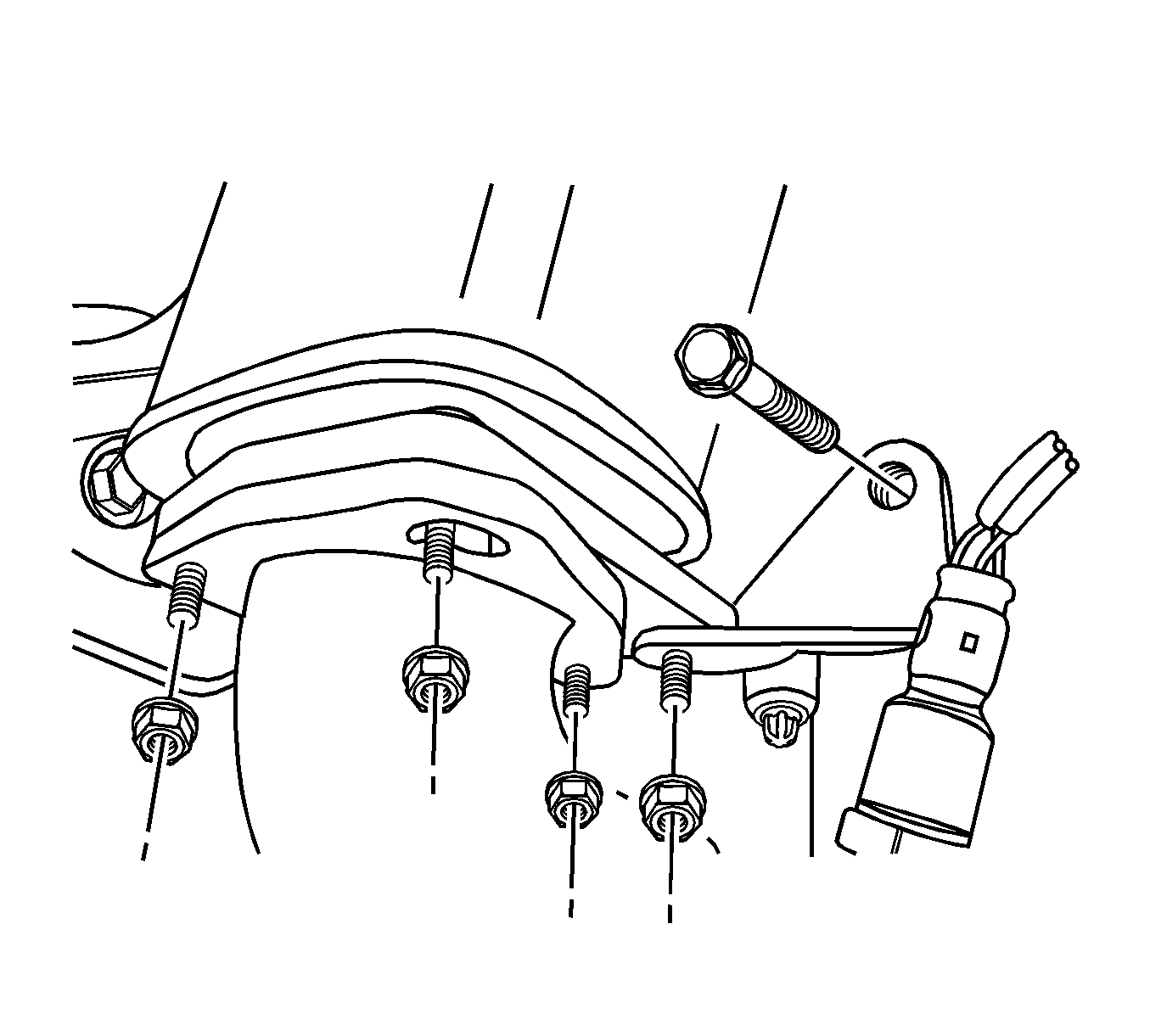
- Remove the pup converter-to-exhaust front pipe retaining nuts.
- Remove the exhaust front pipe mounting bracket bolt and nut.
- Remove the exhaust front pipe from the pup converter. Refer to
Front Pipe Replacement
.
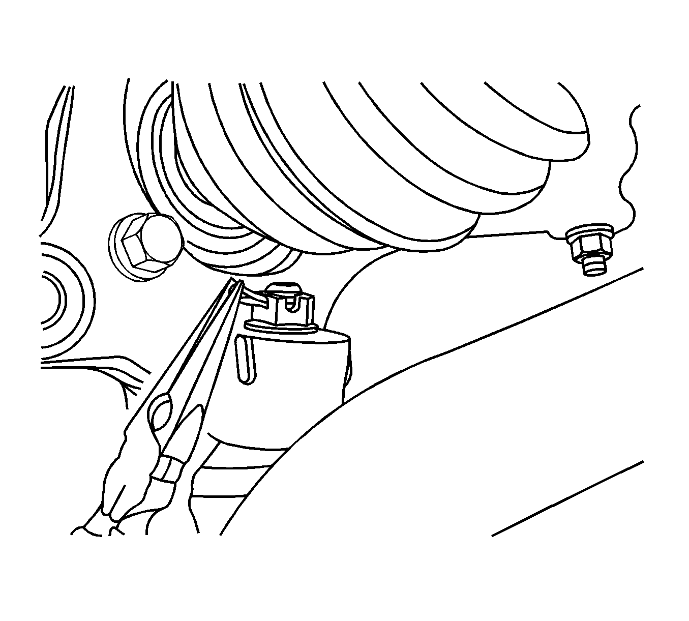
- Disconnect the stabilizer link. Refer to
Stabilizer Shaft Link Replacement
.
- Disconnect the tie rod end joint. Refer to
Steering Linkage Outer Tie Rod Replacement
.
- Disconnect the control arm joint. Refer to
Lower Control Arm Ball Joint Replacement
.
- Remove the left and right axle shaft. Refer to
Front Wheel Drive Shaft Replacement
.
- Remove the power steering gear interm shaft. Refer to
Intermediate Steering Shaft Replacement
.
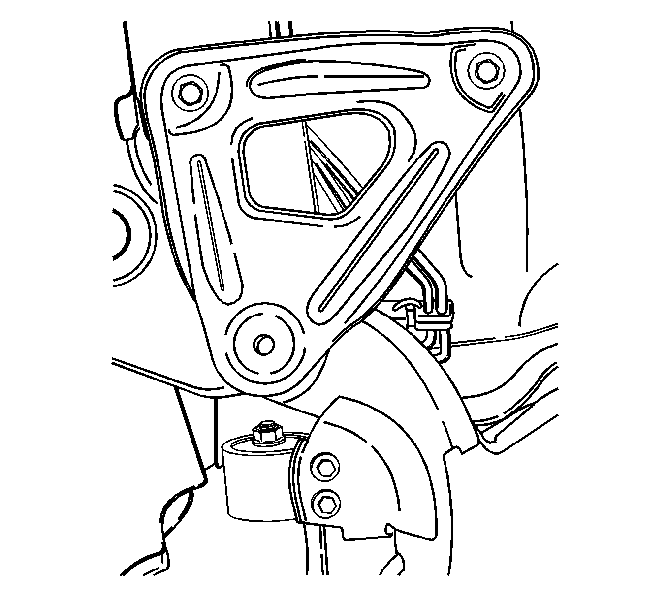
- Remove the cradle support bracket retaining bolts. Refer to
Frame Replacement
.
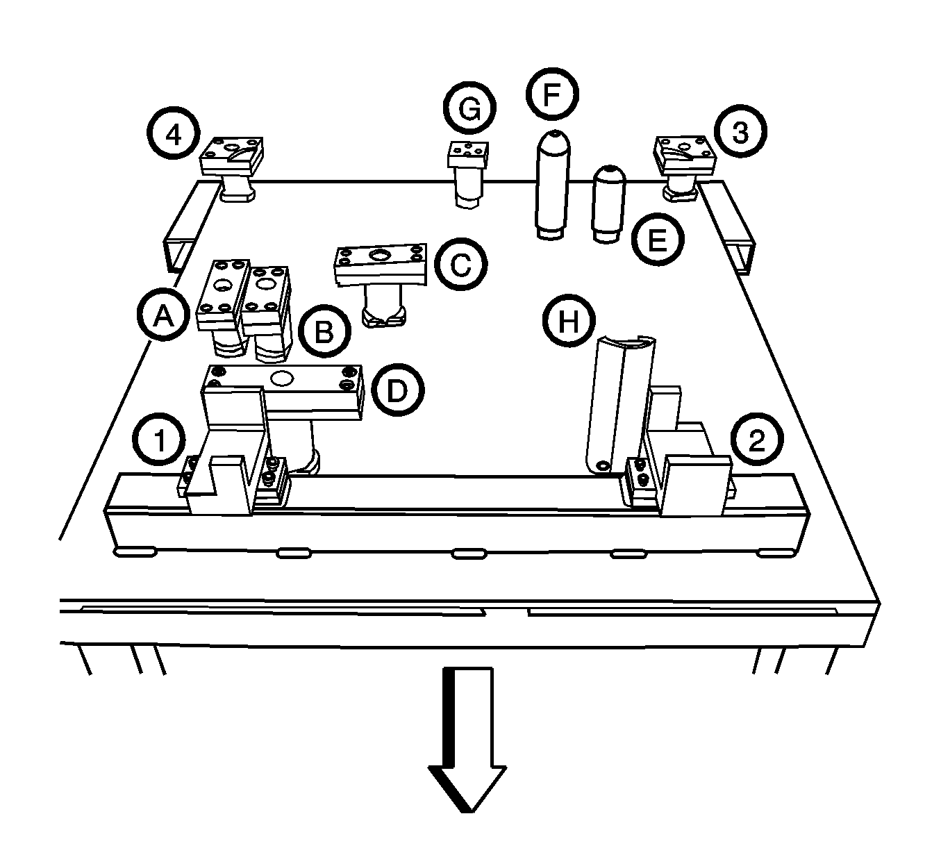
Important: Make sure that all components have to be set on the exact position on the engine assembly remove/install pallet
EN-48243
with the pallet supporter
EN-48244
as
shown.
- Remove the cradle mounting bolts.
| • | Diesel Engine Oil Pan Supporter (A) |
| • | FAM II 2.4D Engine Oil Pan Supporter (B) |
| • | HFV6 3.2L Engine Oil Pan Supporter (C-D) |
| • | Manual Transaxle Supporter (E) |
| • | Automatic Transaxle Supporter (F) |
| • | Power Transaxle Unit (PTU) Supporter (M/T and A/T) (G) |
| • | Transaxle Mount Supporter (M/T and A/T) (H) |
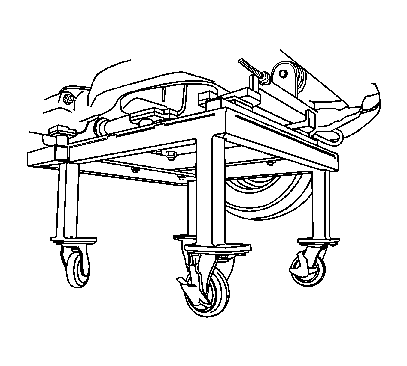
Important: Only lower the vehicle far enough to take the weight off the engine and transaxle mount, or damage to the mount and pallet/pallet supporter failure may occur.
- Lower the vehicle and position the engine assembly on to the
EN-48243
with the
EN-48244
to the cradle.
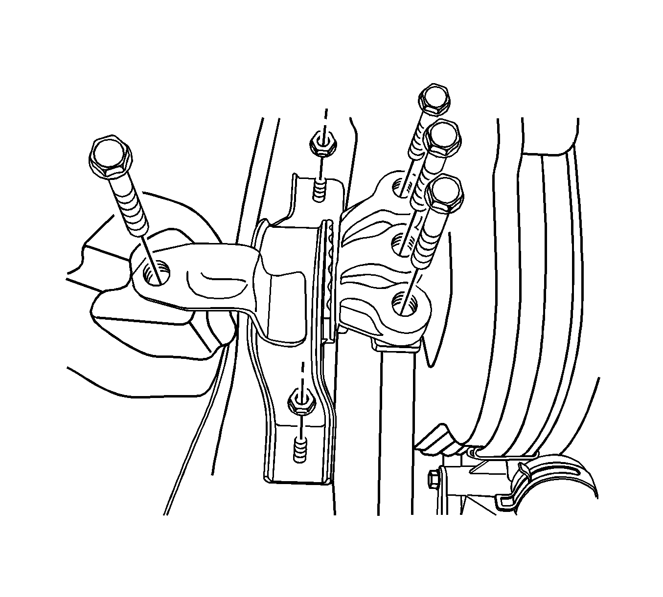
- Remove the engine mount assembly. Refer to
Engine Mount Replacement - Left Side
,
Engine Mount Replacement - Right Side
,
Engine Front Mount Replacement
and
Engine Rear Mount Replacement
.
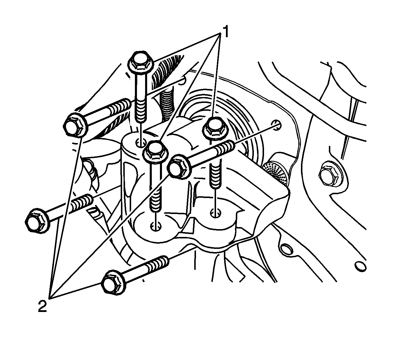
- Remove the transaxle mount assembly. Refer to
Transmission Rear Mount Replacement
and
Transmission Mount Replacement - Left Side
.
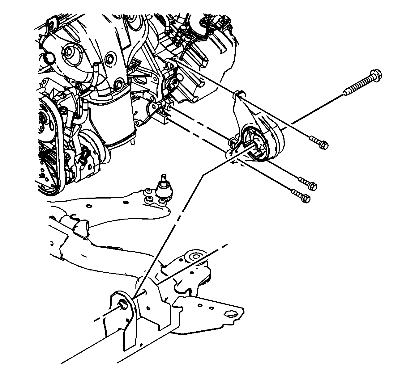
Important: Make sure that all the cables, connectors and hoses are disconnected from the engine and transaxle assembly.
- Raise the vehicle to remove from the engine and transaxle assembly clear.
- Install the hoist to the engine support bracket and lift the engine assembly far enough to take the weight off the transaxle front and rear mount assembly.
- Remove the transaxle front mount assembly from the cradle. Refer to
Transmission Rear Mount Replacement
.
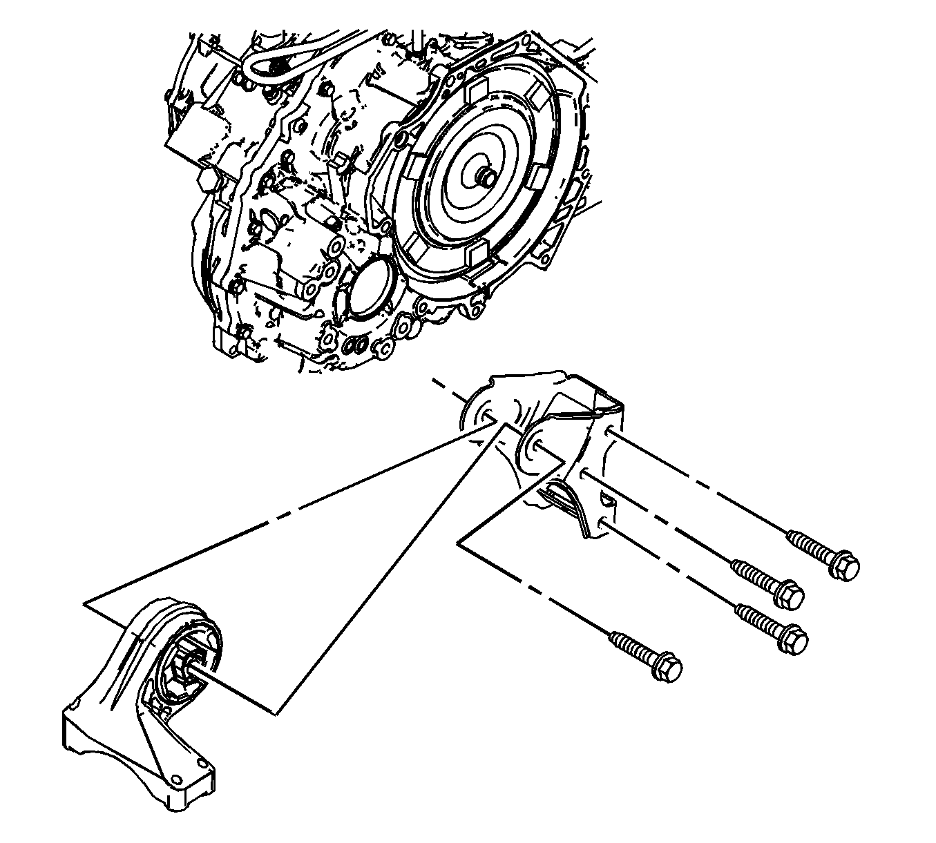
- Remove the transaxle rear mount assembly from the cradle. Refer to
Transmission Mount Replacement - Left Side
.
- Lift the engine assembly and remove the cradle from the engine and transaxle assembly.
- Separate the engine block from the transaxle as follows.
| 44.1. | Remove the torque converter bolts. |
| 44.2. | Remove the transaxle to engine block mounting bolts. |
| 44.3. | Remove the oil flange to transaxle mounting bolts. |
| 44.4. | Remove the starter mounting bolts. |
Installation Procedure
Notice: Refer to Fastener Notice in the Preface section.
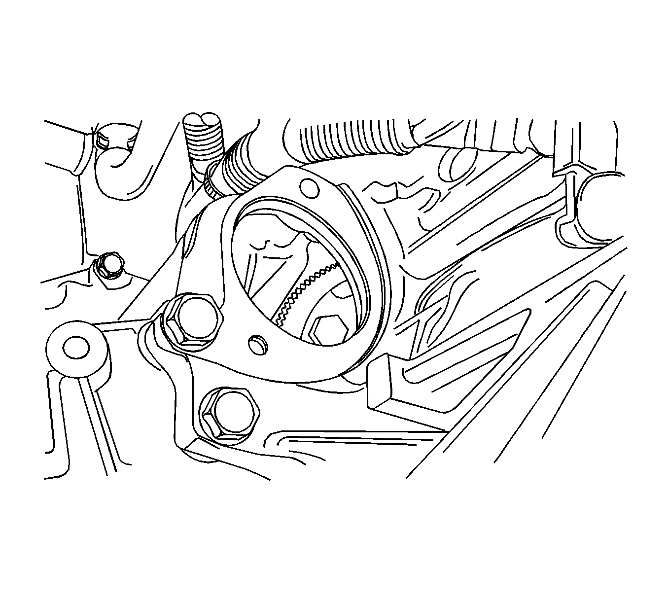
- Install the torque converter bolts.
Tighten
Tighten the torque converter bolts to 45 N·m (33 lb ft).
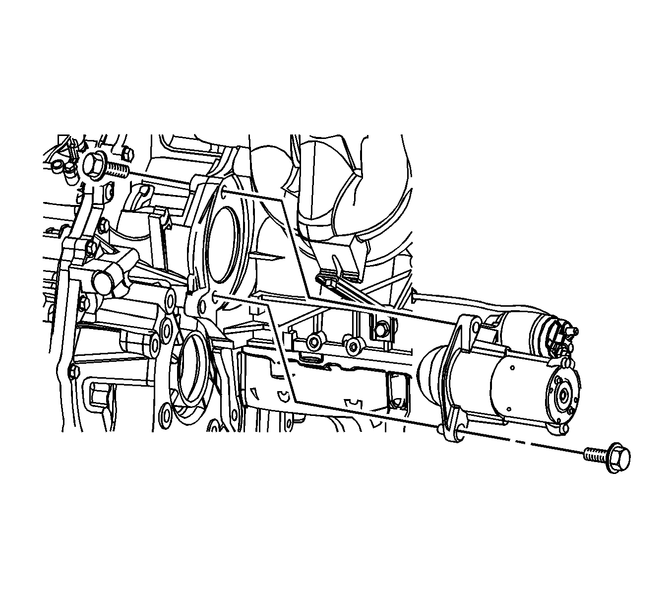
- Install the transaxle to the engine block.
Tighten
| • | Tighten the transaxle bolts to 75 N·m (55 lb ft). |
| • | Tighten the oil pan flange-to-transaxle bolts to 50 N·m (37 lb ft). |
- Install the starter mounting bolts.
Tighten
| • | Tighten the starter-to-engine block mounting bolt to 75 N·m (55 lb ft). |
| • | Tighten the transaxle-to-starter mounting bolt to 75 N·m (55 lb ft). |

Important: Make sure that all components have to be set on the exact position on the engine assembly remove/install pallet
EN-48243
with the pallet supporter
EN-48244
.
Important: Before tightening the transaxle front mount through bolt and nut, swing the engine assembly backwards and forwards or from the side to side for the proper alignment.
- Install the engine and transaxle assembly onto the cradle.
- Install the transaxle front mount assembly.
Tighten
| • | Tighten the transaxle front mount retaining bolts to 50 N·m (37 lb ft). |
| • | Tighten the transaxle front mount-to-transaxle through bolt and nut to 90 N·m (66 lb ft). |

Important: Before tightening the transaxle rear mount through bolt and nut, swing the engine assembly backwards and forwards or from the side to side for the proper alignment.
- Install the transaxle rear mount assembly to the cylinder block.
Tighten
| • | Tighten the transaxle rear mount retaining bolts to 90 N·m (66 lb ft). |
| • | Tighten the transaxle rear mount-to-bracket through bolt and nut to 90 N·m (66 lb ft). |

- Lift the vehicle.
- Lower the vehicle and position the engine and transaxle assembly with the cradle attached on to the
EN-48243
with the
EN-48244
to the vehicle.

- Install the transaxle mount. Refer to
Transmission Rear Mount Replacement
and
Transmission Mount Replacement - Left Side
.
Tighten
| • | Tighten the transaxle mount assembly retaining bolts to 37 N·m (27 lb ft). |
| • | Tighten the transaxle mount bracket retaining bolts to 50 N·m (37 lb ft). |

- Install the engine mount assembly. Refer to
Engine Mount Replacement - Left Side
,
Engine Mount Replacement - Right Side
,
Engine Front Mount Replacement
and
Engine Rear Mount Replacement
.
Tighten
| • | Tighten the engine mount frame side bracket retaining bolt to 100 N·m (74 lb ft). |
| • | Tighten the nuts to 90 N·m (66 lb ft). |
| • | Tighten the engine mount adapter retaining bolts to 50 N·m (37 lb ft). |

- Remove the
EN-48243
with the
EN-48244
from the vehicle.
- Install the cradle-to-body mounting bolts. Refer to
Frame Replacement
.
Tighten
Tighten the cradle mounting bolts to 155 N·m (114 lb ft).
- Install the cradle support bracket retaining bolts. Refer to
Frame Replacement
.
Tighten
Tighten the cradle support bracket bolts to 50 N·m (37 lb ft).

- Install the power steering gear intermediate shaft. Refer to
Intermediate Steering Shaft Replacement
.
- Install the left and right axle shaft. Refer to
Front Wheel Drive Shaft Replacement
.
- Install the control arm joint. Refer to
Lower Control Arm Ball Joint Replacement
.
- Install the tie rod end joint. Refer to
Steering Linkage Outer Tie Rod Replacement
.
- Install the stabilizer link. Refer to
Stabilizer Shaft Link Replacement
.

- Install the exhaust front pipe-to-pup converter. refer to
Front Pipe Replacement
.
Tighten
| • | Tighten the pup converter-to-exhaust front pipe retaining nuts to 40 N·m (30 lb ft). |
| • | Tighten the exhaust front pipe mounting bracket bolt and nut to 40 N·m (30 lb ft). |
- Install the engine electrical wires to the engine.
- Connect all of the necessary vacuum lines, including the brake booster vacuum hose.
- Connect the ground terminals.
- Connect all of the necessary electrical connectors.

- Connect the power steering hoses to the power steering pump. Refer to
Power Steering Pressure Pipe/Hose Replacement
and
Power Steering Return Hose Replacement
.
- Connect the fuel feed line to the fuel rail.

- Connect the heater inlet and outlet hose to the cylinder head.
- Connect all of the necessary cooling hoses to electronic throttle body, thermostat, coolant pipe and cylinder block.
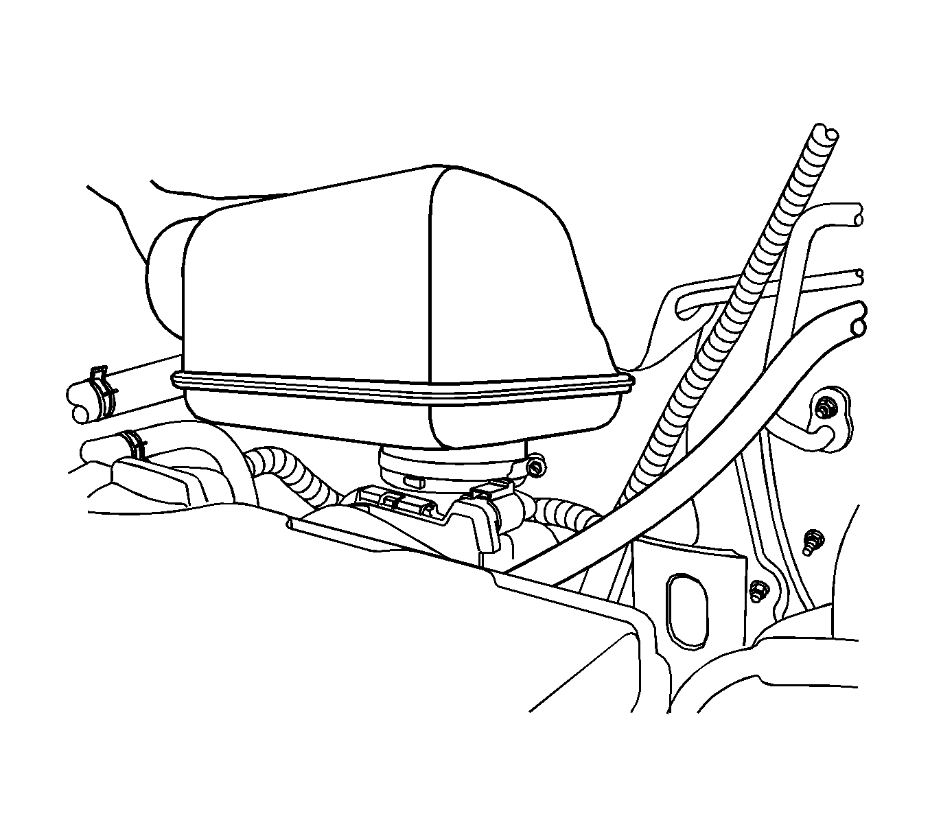
- Install the resonator to the electronic throttle body.

- Install the air cleaner assembly. Refer to
Air Cleaner Assembly Replacement
.
- Install the breather hose and PCV hose to the cylinder head cover.
- Connect the intake air temperature (IAT) sensor connector.
- Install the engine beautification cover.

- Install the fuel pump fuse.
- Refill the engine crankcase with engine oil.
- Refill the engine coolant system. Refer to
Cooling System Draining and Filling
.
- Refill the power steering system and bleed the system. Refer to
Checking and Adding Power Steering Fluid
and
Power Steering System Bleeding
.
- Refill the A/C refrigerant system, if equipped. Refer to
Refrigerant Recovery and Recharging
.


