Special Tools
DW-110-060 Engine Assembly Support Fixture
Removal Procedure
- Raise and suitably support the vehicle and remove the wheels. Refer to Lifting and Jacking the Vehicle and Tire and Wheel Removal and Installation.
- Remove the engine shield from the under body of the vehicle. Refer to Engine Shield Replacement.
- Remove the front control arm ball joint to knuckle nut and pin.
- Remove the front exhaust muffler and catalytic converter. Refer to Muffler Replacement and Resonator Replacement.
- In case of 4-wheel drive vehicle, remove the propeller shaft.
- Remove the outer tie rod to knuckle nut.
- Remove the stabilizer shaft link to strut nut.
- Remove the power steering gear to front suspension crossmember bolts.
- Support the front suspension crossmember by a jack stand.
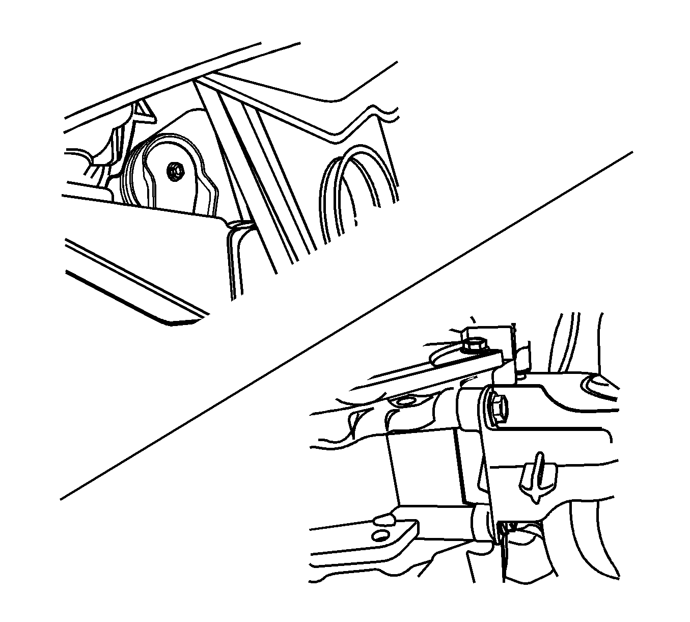
- Remove the front suspension crossmember to transmission rear mount bracket bolts.
- Remove the transmission front mount to front suspension crossmember bolt and remove the mount.
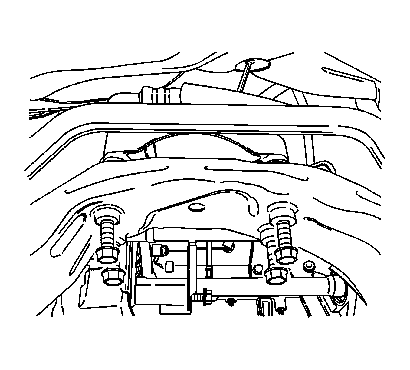
- Remove the front suspension crossmember to body bolts.
- Remove the front suspension crossmember support bracket to body bolts.
- Lower the front suspension crossmember slowly with care. Rotate the stabilizer shaft and tie rod properly to have enough space during lowering the cradle.
- Remove the stabilizer shaft clamp to front suspension crossmember bolts.
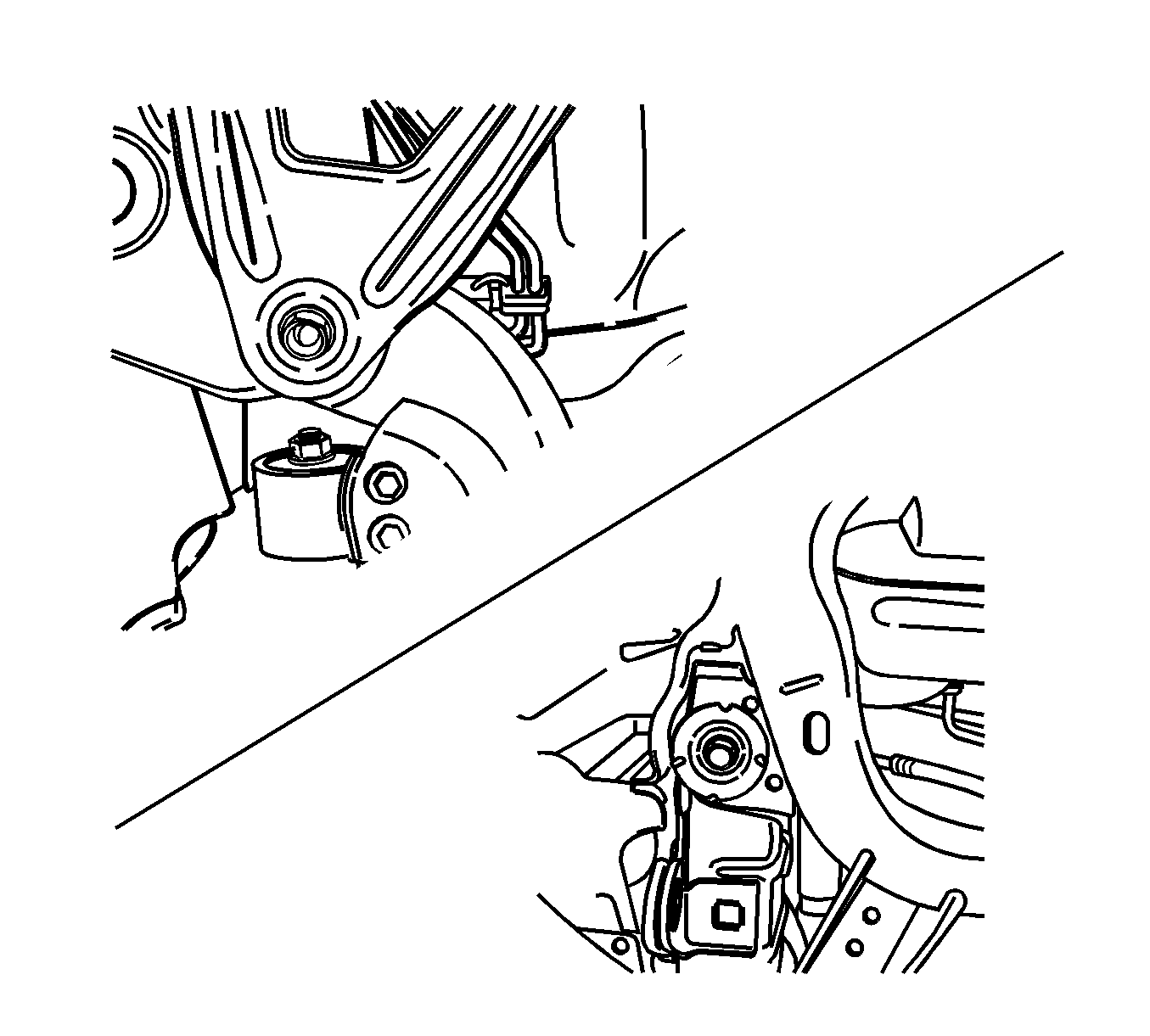
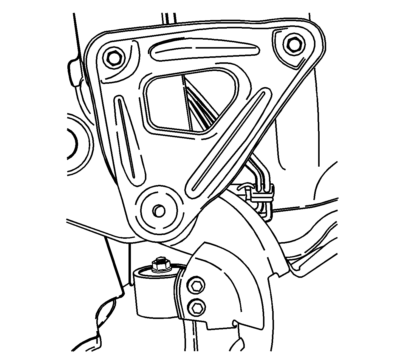
- Remove the control arm to front suspension crossmember bolts and nuts. Refer to Lower Control Arm Replacement.
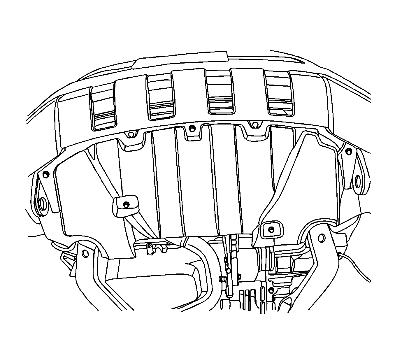
Important: Before raising the vehicle, support the powertrain using the support fixture tool DW-110-060 . This fixture is used to keep the powertrain from rocking fore/aft once the front and rear mounts are disconnected. Remove fixture once cradle is reinstalled.
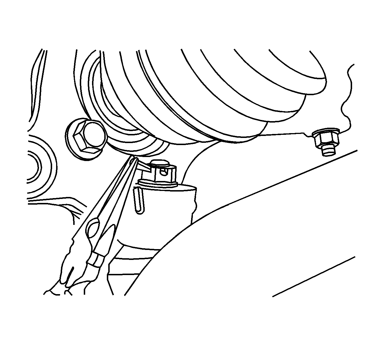
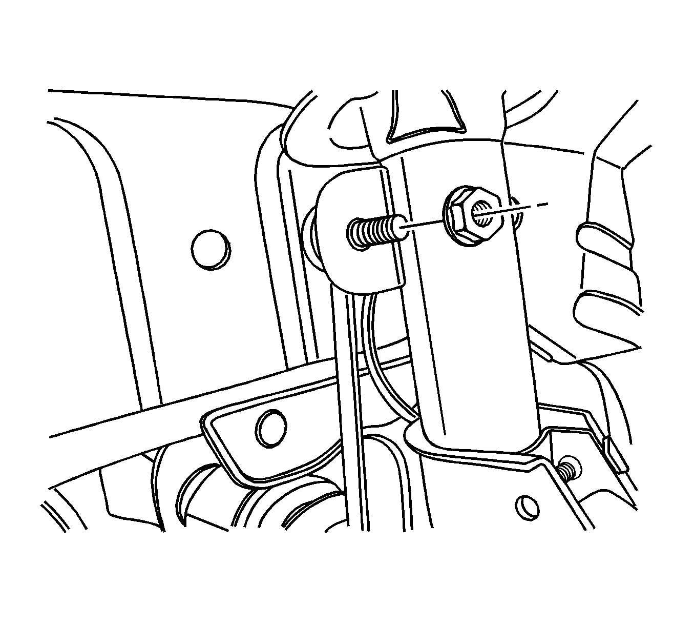
Important: Do not allow the radiator to swing after removing the front suspension crossmember. The upper part of the radiator should be fixed using strings.
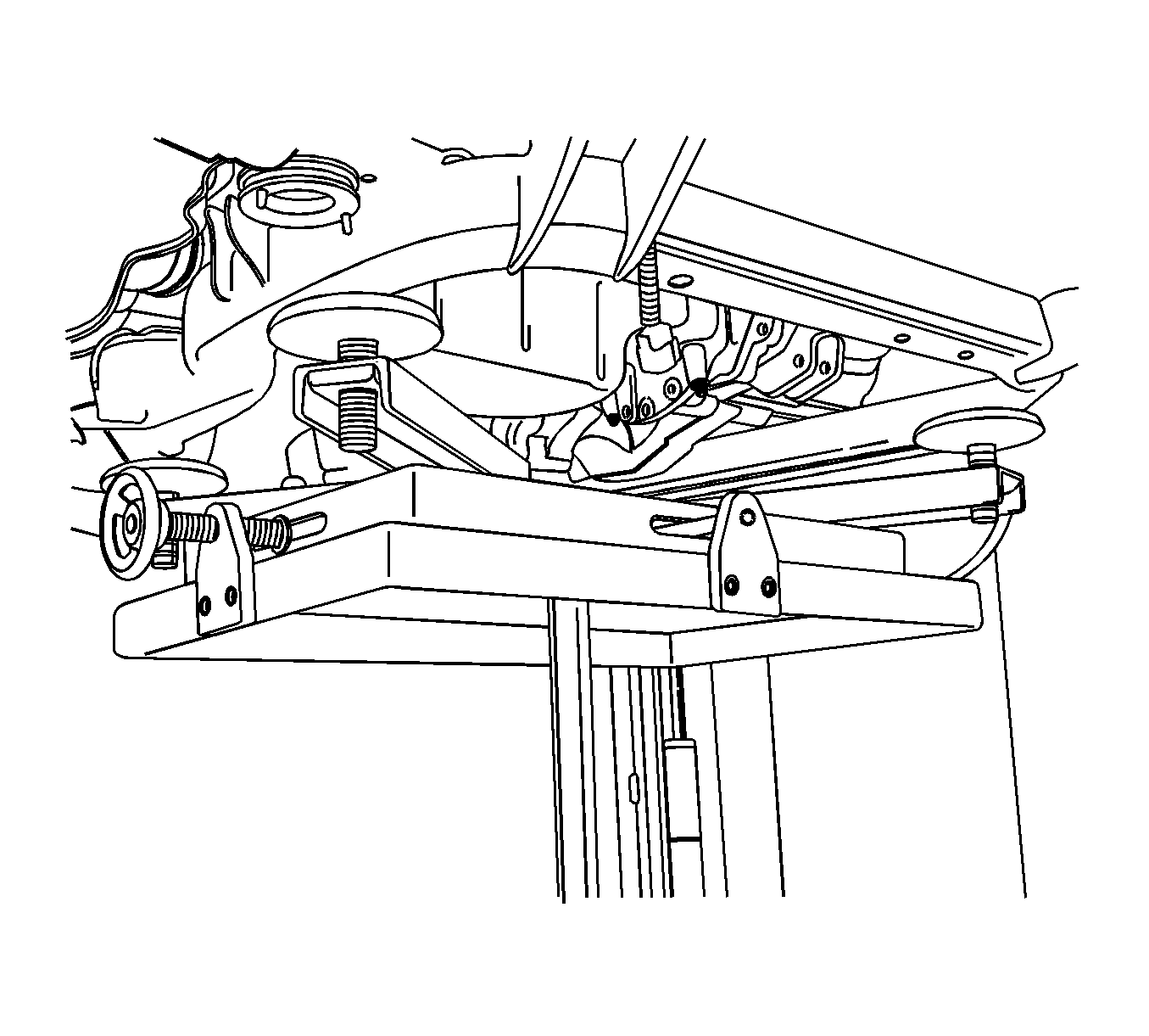
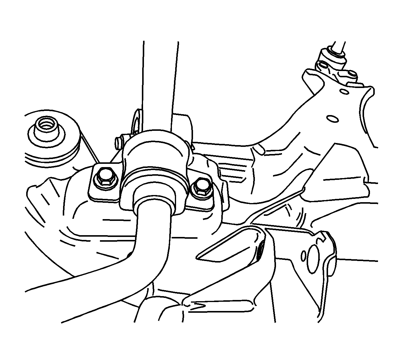
.
Installation Procedure
- Install the front control arm to front suspension crossmember bolts and nuts. Refer to Lower Control Arm Replacement.
- Install the stabilizer shaft clamp to front suspension crossmember bolts.
- Raise the front suspension crossmember slowly with care using a jack stand. Rotate the stabilizer shaft and tie rod properly to settle the front suspension crossmember in the correct position.
- Install the front suspension crossmember support bracket and front suspension crossmember to body bolts.
- Install the front suspension crossmember to transmission rear mount bolts.
- Install the transmission front mount and install the front suspension crossmember to transmission front mount bolt.
- Install the power steering gear to front suspension crossmember bolts.
- Install the stabilizer shaft link to strut nut.
- Install the tie rod to knuckle nut.
- Install the front exhaust muffler and catalytic converter. Refer to Muffler Replacement and Resonator Replacement.
- Install the front control arm ball joint to knuckle nut and pin. Refer to Lower Control Arm Replacement.
- Install the engine shield to the under body of the vehicle. Refer to Engine Shield Replacement.
- Install the wheels. Refer to Tire and Wheel Removal and Installation.
- Lower the vehicle.
- Check vehicle front end alignment. Refer to Wheel Alignment Measurement.
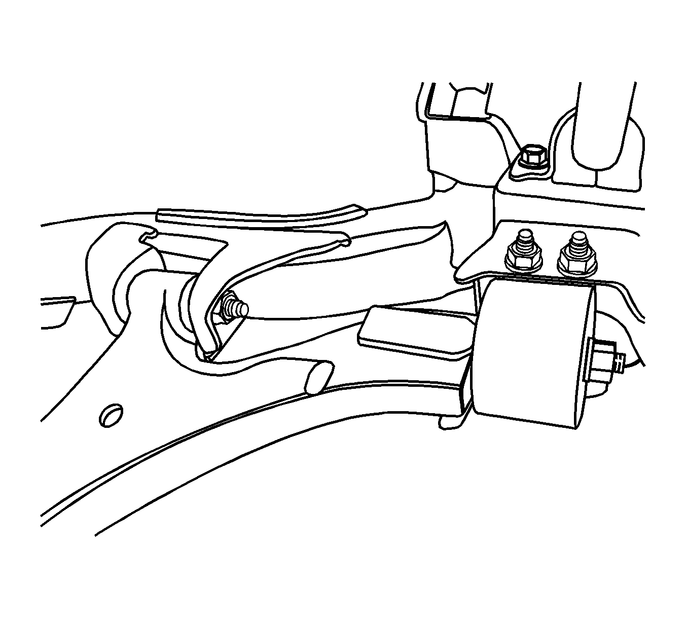
Notice: Refer to Fastener Notice in the Preface section.

Tighten
Tighten the stabilizer shaft clamp bolts to 50 N·m (37 lb ft).

Tighten
| • | Tighten the front suspension crossmember to body bolts to 155 N·m (114 lb ft). |
| • | Tighten the front suspension crossmember support bracket to body bolts to 50 N·m (37 lb ft). |

Tighten
Tighten the front suspension crossmember to transmission rear mount bolts to 110 N·m (81 lb ft).

Tighten
| • | Tighten the transmission front mount to transmission bolts to 50 N·m (37 lb ft). |
| • | Tighten the front suspension crossmember to transmission front mount bolt to 110 N·m (81 lb ft). |

Tighten
Tighten the power steering gear to front suspension crossmember bolts to 110 N·m (81 lb ft).

Tighten
Tighten the stabilizer shaft link nut to 65 N·m (48 lb ft).
Tighten
Tighten the tie rod to knuckle nut to 50 N·m (37 lb ft).


