GM Service Manual Online
For 1990-2009 cars only

Removal Procedure

    Notice: Refer to Engine Emission Notice in the Preface section.

  1. Disconnect the negative battery cable. Refer to Battery Negative Cable Disconnection and Connection in Engine Electrical.
  2. Remove the hood. Refer to Hood Replacement in Body Front End.
  3. Remove the fuel injector sight shield. Refer to Fuel Injector Sight Shield Replacement .
  4. Raise and support the vehicle. Refer to Lifting and Jacking the Vehicle in General Information.
  5. Drain the engine oil. Refer to Engine Oil and Oil Filter Replacement .
  6. Drain the cooling system. Refer to Cooling System Draining and Filling in Engine Cooling.
  7. Remove the torque converter cover. Refer to Torque Converter Cover Replacement in Automatic Transaxle - 4T65-E.
  8. Remove the starter motor. Refer to Starter Motor Replacement in Engine Electrical.
  9. Remove the engine flywheel-to-torque converter bolts. Refer to Flywheel to Torque Converter Bolt Replacement in Automatic Transaxle - 4T65-E.
  10. Scribe the torque converter to the flywheel for installation.
  11. Remove the transaxle brace. Refer to Transmission Brace Replacement in Automatic Transaxle - 4T65-E.

  12. Object Number: 50411  Size: SH
  13. Remove the engine mount lower nuts.

  14. Object Number: 372626  Size: SH
  15. Remove the right exhaust manifold pipe stud nuts from the catalytic converter.
  16. Remove the engine oil level sensor harness retainer bolt.
  17. Remove the engine oil level harness retainer from the engine.
  18. Disconnect and reposition the electrical connectors from the following components:
  19. • Vehicle speed sensor (VSS)
    • Engine oil pressure sensor
    • Engine oil level sensor
    • Knock sensors
    • Heated oxygen sensor (H02S)
  20. Remove the oil filter adapter housing. Refer to Oil Filter Adapter and Bypass Valve Assembly Replacement .
  21. Remove the engine ground nut and engine ground from the transaxle stud.

  22. Object Number: 160965  Size: SH
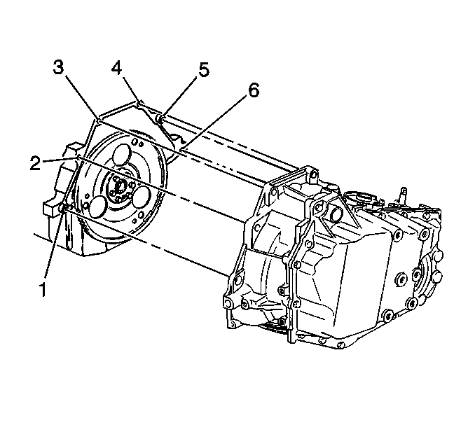
  23. Remove the bolt (6) and the stud (1) which secure the lower transaxle to the engine.
  24. Lower the vehicle while supporting the transaxle.
  25. Remove the air cleaner assembly. Refer to Air Cleaner Assembly Replacement in Engine Controls - 3.8L.

  26. Object Number: 32409  Size: SH

    Important: Relieve the fuel pressure. Refer to Fuel Pressure Relief in Engine Controls - 3.8L.

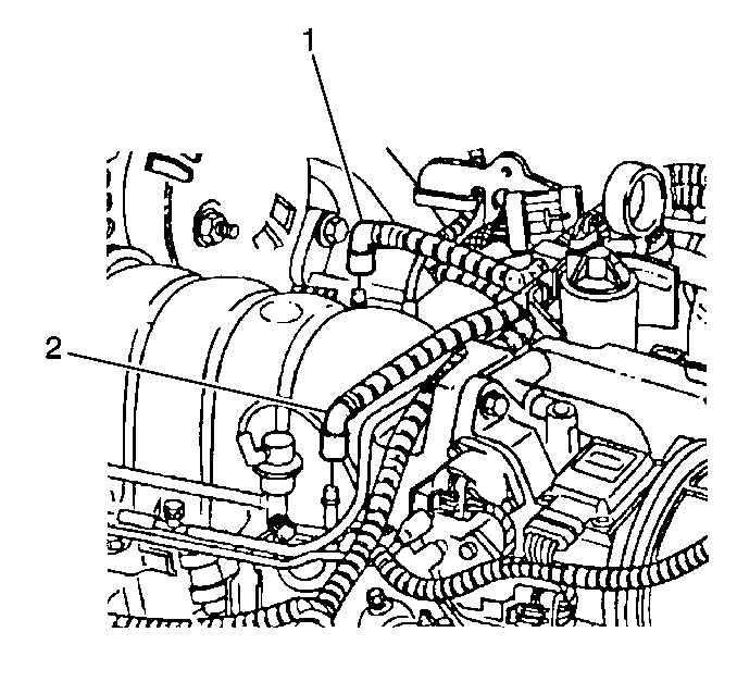
  27. Disconnect the fuel lines (1,2) from the fuel rail. Lay the fuel lines aside. Refer to Fuel Hose/Pipes Replacement - Filter to Engine in Engine Controls - 3.8L.
  28. Disconnect the fuel vapor line.
  29. Remove the throttle and cruise control cables and bracket from the throttle body. Refer to Accelerator Control Cable Bracket Replacement in Engine Controls - 3.8L.

  30. Object Number: 30978  Size: SH
  31. Loosen the water pump pulley bolts.
  32. Remove the drive belt. Refer to Drive Belt Replacement .
  33. Remove the water pump pulley bolts and the water pump pulley.
  34. Remove the right and the left engine mount struts. Refer to Engine Mount Strut Replacement - Right Side and to Engine Mount Strut Replacement - Left Side .
  35. Remove the engine mount strut brackets from the radiator support. Refer to Engine Mount Strut Bracket Replacement - Upper Radiator Support .
  36. Disconnect the positive battery cable.
  37. Remove the fan shroud. Refer to Fan Shroud Replacement in Engine Cooling.
  38. Remove the vacuum booster hose from the engine. Refer to Vacuum Brake Booster Check Valve and/or Hose Replacement in Hydraulic Brakes.
  39. Remove the A/C vacuum hose from the engine.

  40. Object Number: 282122  Size: SH
  41. Remove the power steering pump and the power steering bolts from the engine. Lay the power steering pump aside.
  42. Disconnect the upper engine electrical connectors from the following components:
  43. • Fuel injectors
    • Throttle position (T/P) sensor
    • Idle air control (IAC) valve
    • EVAP purge solenoid
    • Exhaust gas recirculation (EGR) valve
    • Manifold absolute pressure (MAP) sensor
  44. Remove upper engine wiring harness from retaining clips and reposition the engine wiring harness for engine removal.
  45. Remove the radiator inlet hose from the engine. Refer to Radiator Inlet Hose Replacement in Engine Cooling.
  46. Remove the radiator outlet hose from the water pump. Refer to Radiator Outlet Hose Replacement in Engine Cooling.
  47. Remove the heater hoses from the drive belt tensioner. Refer to Heater Inlet Hose Replacement and to Heater Outlet Hose Replacement in Heating, Ventilation and Air Conditioning.

  48. Object Number: 277915  Size: SH
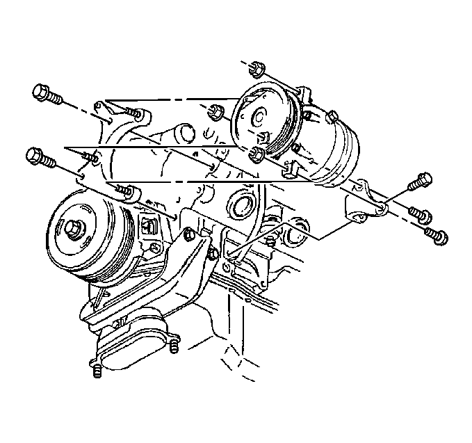
  49. Remove the A/C compressor nuts and the A/C compressor from the engine. DO NOT discharge the A/C system. Secure the compressor to the frame.
  50. Install the engine lifting device.

  51. Object Number: 160965  Size: SH
  52. Remove the bolts (2,3,4,5) which secure the upper transaxle to the engine.
  53. With the aid of an assistant, remove the engine from the vehicle.
  54. Remove the flywheel. Refer to Engine Flywheel Replacement .
  55. Install the engine to the engine stand.

  56. Object Number: 405812  Size: SH
  57. Remove the oil level indicator tube nut from the exhaust manifold.
  58. Remove the oil level indicator tube.
  59. Remove the engine mount bracket with the engine mount. Refer to Engine Mount and Bracket Replacement .
  60. Remove the drive belt tensioner. Refer to Drive Belt Tensioner Replacement .
  61. Remove the ignition control module and the ignition control module bracket. Refer to Ignition Control Module Replacement in Engine Controls - 3.8L.
  62. Remove the left and right side engine mount brackets. Refer to Engine Mount Strut Bracket Replacement - Left Side and to Engine Mount Strut Bracket Replacement - Right Upper .

  63. Object Number: 277915  Size: SH
  64. Remove the A/C compressor mounting bracket bolts and the A/C compressor bracket.

  65. Object Number: 371090  Size: SH
  66. Remove the fuel injector sight shield bracket nuts.
  67. Remove the fuel injector sight shield bracket
  68. Remove the EGR valve adapter from the right cylinder head. Refer to Exhaust Gas Recirculation Inlet Pipe Replacement in Engine Controls - 3.8L.
  69. Remove the upper intake manifold. Refer to Upper Intake Manifold Replacement .

  70. Object Number: 371022  Size: SH
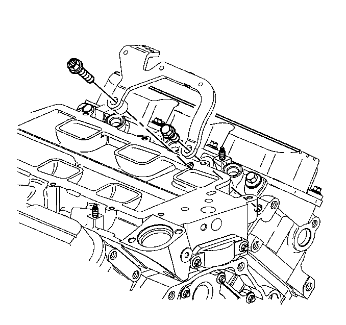
  71. Remove the generator brace bracket bolts.
  72. Remove the generator brace bracket from the right cylinder head.
  73. Remove the engine lift brackets.
  74. Remove the crankshaft balancer. Refer to Crankshaft Balancer Replacement .
  75. Remove the right exhaust manifold, the left exhaust manifold and the exhaust crossover. Refer to Exhaust Manifold Replacement - Right Side and to Exhaust Manifold Replacement - Left Side in Engine Exhaust.

Installation Procedure

    Notice: Refer to Engine Emission Notice in the Preface section.

  1. Install the right exhaust manifold, the left exhaust manifold and the exhaust crossover. Refer to Exhaust Manifold Replacement - Right Side and Exhaust Manifold Replacement - Left Side in Engine Exhaust.
  2. Install the crankshaft balancer. Refer to Crankshaft Balancer Replacement .
  3. Notice: Use the correct fastener in the correct location. Replacement fasteners must be the correct part number for that application. Fasteners requiring replacement or fasteners requiring the use of thread locking compound or sealant are identified in the service procedure. Do not use paints, lubricants, or corrosion inhibitors on fasteners or fastener joint surfaces unless specified. These coatings affect fastener torque and joint clamping force and may damage the fastener. Use the correct tightening sequence and specifications when installing fasteners in order to avoid damage to parts and systems.

  4. Install the engine lift brackets.
  5. Install the bolts and the nuts to the engine lift brackets.
  6. Tighten
    Tighten the bolts and the nuts to 30 N·m (22 lb ft).

    Object Number: 371022  Size: SH
  7. Install the generator brace bracket to the right cylinder head.
  8. Install the generator brace bracket bolts.
  9. Tighten
    Tighten the bolts to 50 N·m (37 lb ft).

  10. Install the upper intake manifold. Refer to Upper Intake Manifold Replacement .
  11. Install the EGR valve adapter to the right cylinder head. Refer to Exhaust Gas Recirculation Inlet Pipe Replacement in Engine Controls - 3.8L.

  12. Object Number: 371090  Size: SH
  13. Install the fuel injector sight shield bracket.
  14. Install the fuel injector sight shield bracket nuts.
  15. Tighten
    Tighten the nuts to 30 N·m (22 lb ft).

    Object Number: 277915  Size: SH
  16. Install the A/C compressor mounting bracket.
  17. Install the A/C compressor bracket bolts.
  18. Tighten
    Tighten the bolts to 50 N·m (37 lb ft).

  19. Install the left and right side engine mount brackets. Refer to Engine Mount Strut Bracket Replacement - Left Side and to Engine Mount Strut Bracket Replacement - Right Upper .
  20. Install the ignition control module bracket and the ignition control module. Refer to Ignition Control Module Replacement in Engine Controls - 3.8L.
  21. Install the drive belt tensioner. Refer to Drive Belt Tensioner Replacement .
  22. Install the engine mount bracket with the engine mount to the engine. Refer to Engine Mount and Bracket Replacement .

  23. Object Number: 405812  Size: SH
  24. Ensure that the O-ring is in place and Install the oil level indicator tube to the engine.
  25. Install the tube nut on the oil level indicator to the exhaust manifold stud.
  26. Tighten
    Tighten the nut to 19 N·m (14 lb ft).

  27. Remove the engine from the engine stand.
  28. Install the flywheel. Refer to Engine Flywheel Replacement .
  29. With the aid of an assistant install the engine to the vehicle.
  30. Object Number: 160965  Size: SH
  31. Install the bolts (2,3,4,5) which secure the upper transaxle to the engine.
  32. Tighten
    Tighten the bolts to 75 N·m (55 lb ft).

  33. Remove the engine lifting device.

  34. Object Number: 277915  Size: SH
  35. Install the A/C compressor to the engine.
  36. Install the mounting nuts to the A/C compressor.
  37. Tighten
    Tighten the nuts to 30 N·m (22 lb ft).

  38. Install the heater hoses to the drive belt tensioner. Refer to Heater Inlet Hose Replacement and to Heater Outlet Hose Replacement in Heating, Ventilation and Air Conditioning.
  39. Install the radiator outlet hose to the water pump. Refer to Radiator Outlet Hose Replacement in Engine Cooling.
  40. Install the radiator inlet hose to the engine. Refer to Radiator Inlet Hose Replacement in Engine Cooling.
  41. Reposition the engine wiring to the engine.
  42. Connect the upper engine electrical connectors to the following components:
  43. • Manifold absolute pressure (MAP) sensor
    • Exhaust gas recirculation (EGR) valve
    • EVAP purge solenoid
    • Idle air control (IAC) valve
    • Throttle position (T/P) sensor
    • Fuel injectors
  44. Install the upper engine wiring harness to the retaining clips.
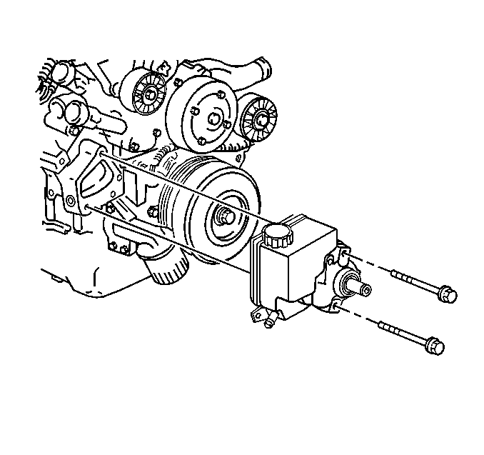
  45. Object Number: 282122  Size: SH
  46. Install the power steering pump.
  47. Install the power steering pump bolts.
  48. Tighten
    Tighten the bolts to 34 N·m (25 lb ft).

  49. Connect the A/C vacuum hose to the engine.
  50. Install the vacuum booster hose to the engine. Refer to Vacuum Brake Booster Check Valve and/or Hose Replacement in Hydraulic Brakes.
  51. Install the fan shroud. Refer to Fan Shroud Replacement in Engine Cooling.
  52. Connect the positive battery cable.
  53. Tighten
    Tighten the positive terminal bolt to 15 N·m (11 lb ft).

  54. Install the engine mount brackets to the radiator support. Refer to Engine Mount Strut Bracket Replacement - Upper Radiator Support .
  55. Install the right and the left engine mount struts. Refer to Engine Mount Strut Replacement - Right Side and Engine Mount Strut Replacement - Left Side .
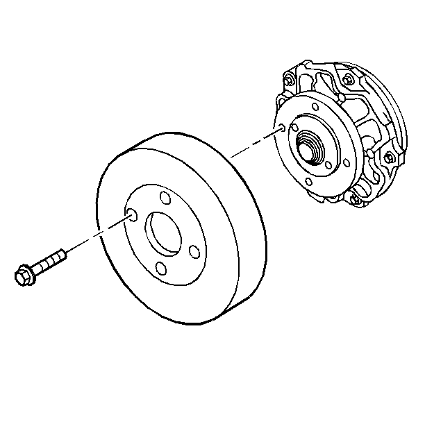
  56. Object Number: 30978  Size: SH
  57. Install the water pump pulley.
  58. Install the water pump pulley bolts.
  59. Tighten
    Tighten the bolts to 13 N·m (116 lb in).

  60. Install the drive belt. Refer to Drive Belt Replacement .
  61. Install the throttle cable, the cruise control cable and bracket to the throttle body. Refer to Accelerator Control Cable Bracket Replacement in Engine Controls - 3.8L.
  62. Connect the fuel vapor line.

  63. Object Number: 32409  Size: SH
  64. Connect the fuel lines (1,2) to the fuel rail.
  65. Install the air cleaner assembly. Refer to Air Cleaner Assembly Replacement in Engine Controls-3.8L.
  66. Raise the vehicle and remove the transaxle support.

  67. Object Number: 160965  Size: SH
  68. Install the bolt (6) and the stud (1) which secure the lower transaxle to the engine.
  69. Tighten
    Tighten the bolt and the stud to 75 N·m (55 lb ft).

  70. Install the engine ground to the transaxle stud.
  71. Install the engine ground nut.
  72. Tighten
    Tighten the nut to 35 N·m (26 lb ft).

  73. Install the oil filter adapter housing. Refer to Oil Filter Adapter and Bypass Valve Assembly Replacement .
  74. Reposition and connect the electrical connectors to the following components:
  75. • Heated oxygen sensor (H02S)
    • Knock sensors
    • Engine oil level sensor
    • Engine oil pressure sensor
    • Vehicle speed sensor (VSS)
  76. Install the engine oil level sensor harness retainer.
  77. Install the engine oil level sensor harness retainer bolt.
  78. Tighten
    Tighten the bolt to 10 N·m (89 lb in).
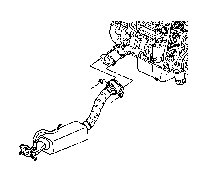

    Object Number: 372626  Size: SH
  79. Install the catalytic converter pipe to the right exhaust manifold.
  80. Install the stud nuts to the right exhaust manifold.
  81. Tighten
    Tighten the nuts to 32 N·m (24 lb ft).
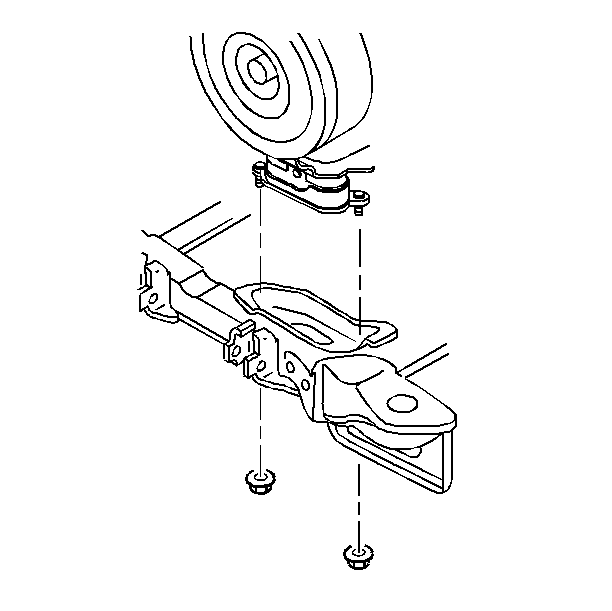

    Object Number: 50411  Size: SH
  82. Install the lower nuts to the engine mount.
  83. Tighten
    Tighten the nuts to 78 N·m (58 lb ft).

  84. Install the transaxle brace. Refer to Transmission Brace Replacement in Automatic Transaxle - 4T65-E.
  85. Install the engine flywheel-to-torque converter bolts. Refer to Flywheel to Torque Converter Bolt Replacement in Automatic Transaxle - 4T65-E.
  86. Install the starter motor. Refer to Starter Motor Replacement in Engine Electrical.
  87. Install the torque converter cover. Refer to Torque Converter Cover Replacement in Automatic Transaxle - 4T65-E.
  88. Lower the vehicle.
  89. Install the fuel injector sight shield. Refer to Fuel Injector Sight Shield Replacement .
  90. Install the hood. Refer to Hood Replacement in Body Front End.
  91. Connect the negative battery cable. Refer to Battery Negative Cable Disconnection and Connection in Engine Electrical.
  92. Fill the crankcase with engine oil. Refer to Engine Oil and Oil Filter Replacement .
  93. Fill the cooling system. Refer to Cooling System Draining and Filling in Engine Cooling.
  94. Inspect for leaks.
  95. Perform the CKP system variation learn procedure. Refer to Crankshaft Position System Variation Learn in Engine Controls - 3.8L.