Valve Rocker Arm Cover Replacement Engine Left Side
Removal Procedure
- Disconnect the battery ground (negative) cable. Refer to Battery Negative Cable Disconnection and Connection in Engine Electrical.
- Remove the fuel injector sight shield. Refer to Fuel Injector Sight Shield Replacement .
- Disconnect the left (front) spark plug wires. Refer to Spark Plug Wire Harness Replacement in Engine Electrical.
- Remove the automatic transaxle vacuum modulator pipe. Refer to Vacuum Modulator Pipe Replacement in Automatic Transmission/Transaxle.
- Remove the right engine mount strut at the engine. Refer to Engine Mount Strut Replacement .
- Remove the Positive Crankcase Ventilation (PCV) valve from the left (front) valve rocker arm cover.
- Remove the left (front) valve rocker arm cover bolts.
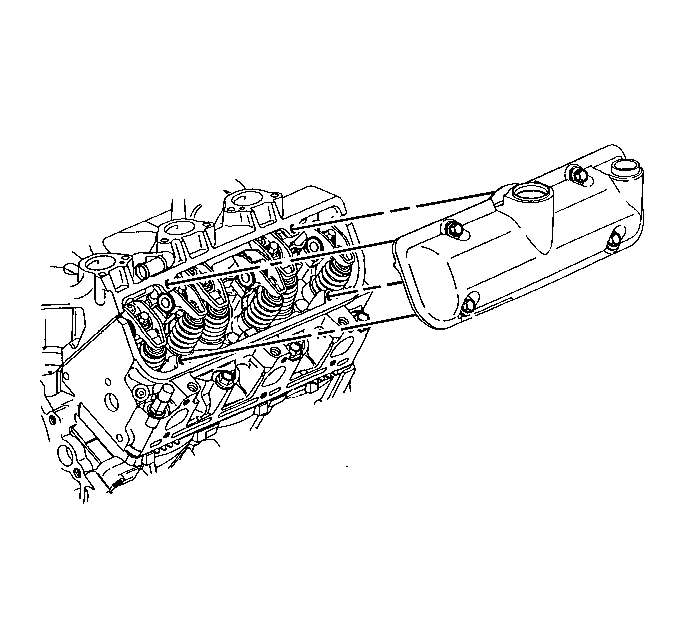
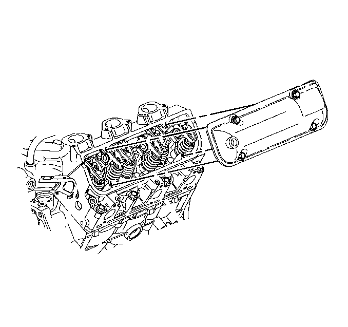
- Remove the left (front) valve rocker arm cover.
- Remove the left (front) valve rocker arm cover gasket.
- Clean the valve rocker arm cover. Refer to Valve Rocker Arm Cover Clean and Inspect .
- Clean the valve rocker arm cover gasket sealing surfaces on the cylinder head and the lower intake manifold.
Installation Procedure
- Install a new left (front) valve rocker arm cover gasket.
- Apply sealant at the cylinder head to lower intake manifold joint at the rear of the lower intake manifold (1).
- Apply sealant at the cylinder head to lower intake manifold joint at the front of the lower intake manifold (1).
- Install the left (front) valve rocker arm cover.
- Install the Positive Crankcase Ventilation (PCV) valve to the left (front) valve rocker arm cover.
- Install the right engine mount strut at the engine. Refer to Engine Mount Strut Replacement .
- Connect the automatic transaxle vacuum modulator pipe. Refer to Vacuum Modulator Pipe Replacement in Automatic Transmission/Transaxle.
- Connect the left (front) spark plug wires. Refer to Spark Plug Wire Harness Replacement in Engine Electrical.
- Install the fuel injector sight shield. Refer to Fuel Injector Sight Shield Replacement .
- Connect the battery ground (negative) cable. Refer to Battery Negative Cable Disconnection and Connection in Engine Electrical.
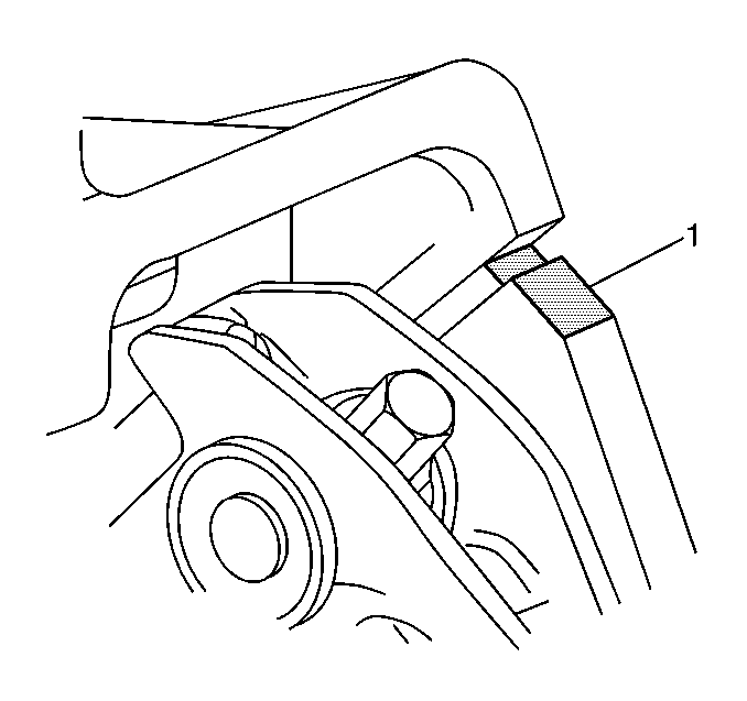
Important: Apply sealant GM P/N 12345739 or equivalent at the cylinder head to lower intake manifold joint.
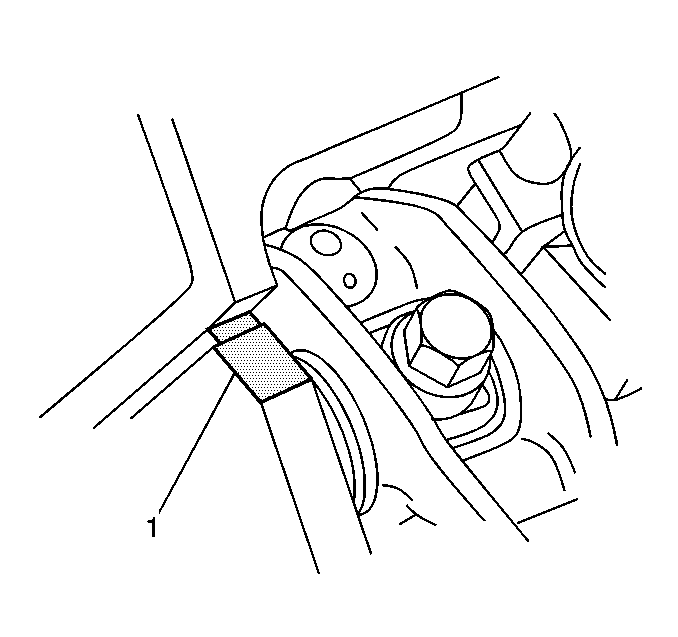
Important: Apply sealant GM P/N 12345739 or equivalent at the cylinder head to lower intake manifold joint.
Notice: Use the correct fastener in the correct location. Replacement fasteners must be the correct part number for that application. Fasteners requiring replacement or fasteners requiring the use of thread locking compound or sealant are identified in the service procedure. Do not use paints, lubricants, or corrosion inhibitors on fasteners or fastener joint surfaces unless specified. These coatings affect fastener torque and joint clamping force and may damage the fastener. Use the correct tightening sequence and specifications when installing fasteners in order to avoid damage to parts and systems.
Hand tighten the left (front) valve rocker arm cover bolts.
Tighten
Tighten the valve rocker arm cover bolts to 10 N·m (89 lb in).
Valve Rocker Arm Cover Replacement Engine Right Side
Removal Procedure
- Disconnect the battery ground (negative) cable. Refer to Battery Negative Cable Disconnection and Connection in Engine Electrical.
- Remove the fuel injector sight shield. Refer to Fuel Injector Sight Shield Replacement .
- Remove the drive belt. Refer to Drive Belt Replacement .
- Remove the generator front brace. Refer to Generator Brace Replacement in Engine Electrical.
- Remove the generator rear brace. Refer to Generator Brace Replacement in Engine Electrical.
- Remove the generator. Refer to Generator Replacement in Engine Electrical.
- Remove the generator bracket. Refer to Generator Bracket Replacement in Engine Electrical.
- Disconnect the right (rear) spark plug wires. Refer to Spark Plug Wire Harness Replacement in Engine Electrical.
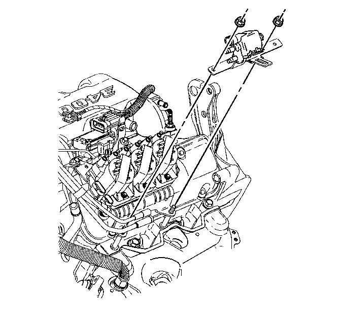
- Disconnect the vacuum hoses from the evaporative emission canister purge solenoid valve.
- Remove the evaporative emission canister purge solenoid valve. Refer to Evaporative Emission Canister Purge Solenoid Valve Replacement in Engine Controls - 3.4L.
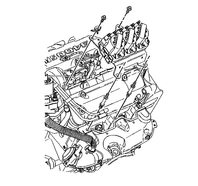
- Remove the ignition coil bracket with the coils. Refer to Ignition Control Module Replacement in Engine Controls - 3.4L.
- Remove the vacuum hose from the grommet in the right (rear) valve rocker arm cover.
- Remove the right (rear) valve rocker arm cover bolts.
- Remove the right (rear) valve rocker arm cover.
- Remove the right (rear) valve rocker arm cover gasket.
- Clean the valve rocker arm cover. Refer to Valve Rocker Arm Cover Clean and Inspect .
- Clean the valve rocker arm cover gasket sealing surfaces on the cylinder head and the lower intake manifold.
Installation Procedure
- Install a new right (rear) valve rocker arm cover gasket.
- Apply sealant at the cylinder head to lower intake manifold joint at the rear of the lower intake manifold (1).
- Apply sealant at the cylinder head to lower intake manifold joint at the front of the lower intake manifold (1).
- Install the right (rear) valve rocker arm cover.
- Install the vacuum hose to the grommet in the right (rear) valve rocker arm cover.
- Install the ignition coil bracket with coils. Refer to Ignition Control Module Replacement in Engine Controls - 3.4L.
- Install the evaporative emission canister purge solenoid valve. Refer to Evaporative Emission Canister Purge Solenoid Valve Replacement in Engine Controls - 3.4L.
- Connect the vacuum hoses from the evaporative emission canister purge solenoid valve.
- Connect the right (rear) spark plug wires. Refer to Spark Plug Wire Harness Replacement in Engine Electrical.
- Install the generator bracket. Refer to Generator Bracket Replacement in Engine Electrical.
- Install the generator. Refer to Generator Replacement in Engine Electrical.
- Install the generator rear brace. Refer to Generator Brace Replacement in Engine Electrical.
- Install the generator front brace. Refer to Generator Brace Replacement in Engine Electrical.
- Install the drive belt. Refer to Drive Belt Replacement .
- Install the fuel injector sight shield. Refer to Fuel Injector Sight Shield Replacement .
- Connect the battery ground (negative) cable. Refer to Battery Negative Cable Disconnection and Connection in Engine Electrical.
Important: Apply sealant GM P/N 12345739 or equivalent at the cylinder head to lower intake manifold joint.
Important: Apply sealant GM P/N 12345739 or equivalent at the cylinder head to lower intake manifold joint.
Notice: Use the correct fastener in the correct location. Replacement fasteners must be the correct part number for that application. Fasteners requiring replacement or fasteners requiring the use of thread locking compound or sealant are identified in the service procedure. Do not use paints, lubricants, or corrosion inhibitors on fasteners or fastener joint surfaces unless specified. These coatings affect fastener torque and joint clamping force and may damage the fastener. Use the correct tightening sequence and specifications when installing fasteners in order to avoid damage to parts and systems.
Hand tighten the right (rear) valve rocker arm cover bolts.
Tighten
Tighten the valve rocker arm cover bolts to 10 N·m (89 lb in).
