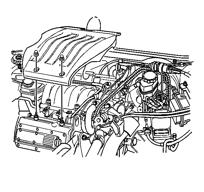
- Install the intake manifold.
- Install the throttle body
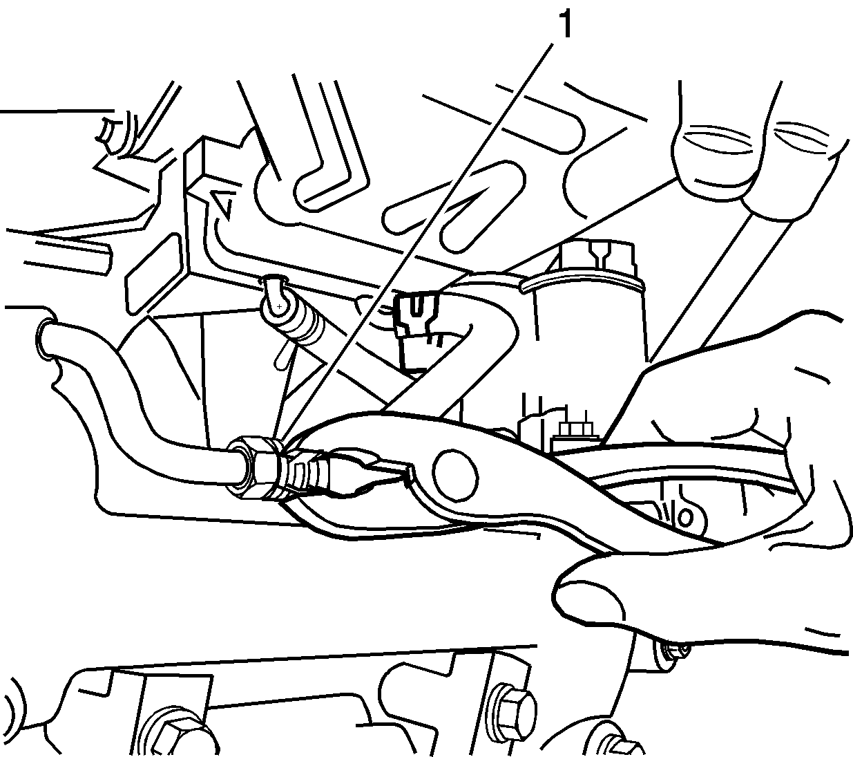
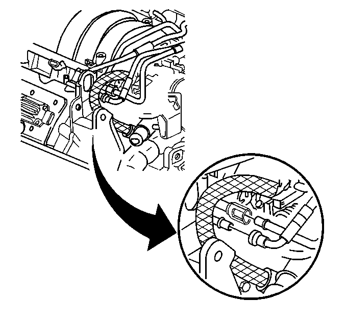
heater hose to the water crossover feed tube (1).
- Install the hose clamp.
Notice: Use the correct fastener in the correct location. Replacement fasteners
must be the correct part number for that application. Fasteners requiring
replacement or fasteners requiring the use of thread locking compound or sealant
are identified in the service procedure. Do not use paints, lubricants, or
corrosion inhibitors on fasteners or fastener joint surfaces unless specified.
These coatings affect fastener torque and joint clamping force and may damage
the fastener. Use the correct tightening sequence and specifications when
installing fasteners in order to avoid damage to parts and systems.
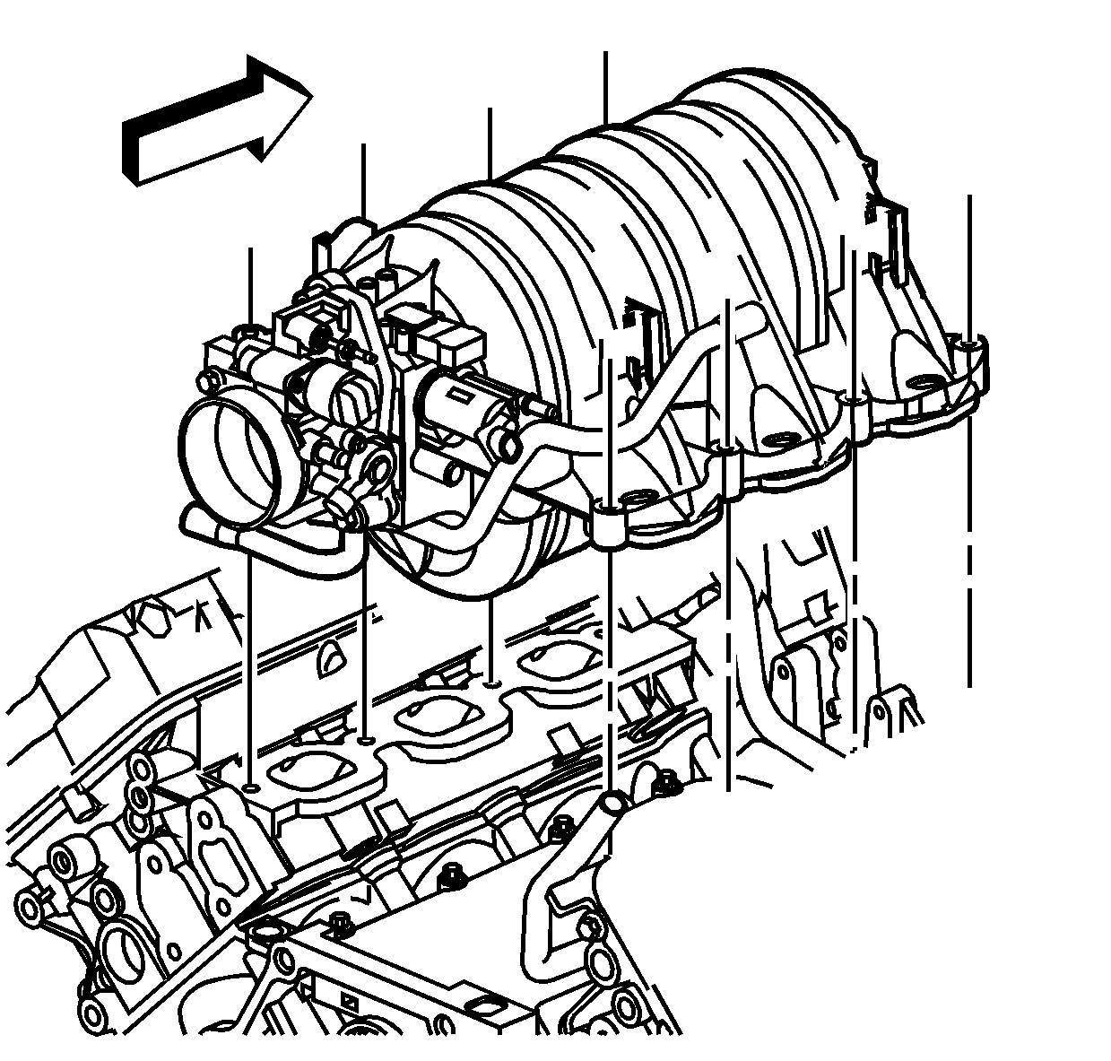
- Install the intake manifold bolts.
Important: Tighten the intake manifold bolts in circular pattern starting from
the center and moving outward.
Tighten
Tighten the intake manifold bolts to 7 N·m (62 lb in).
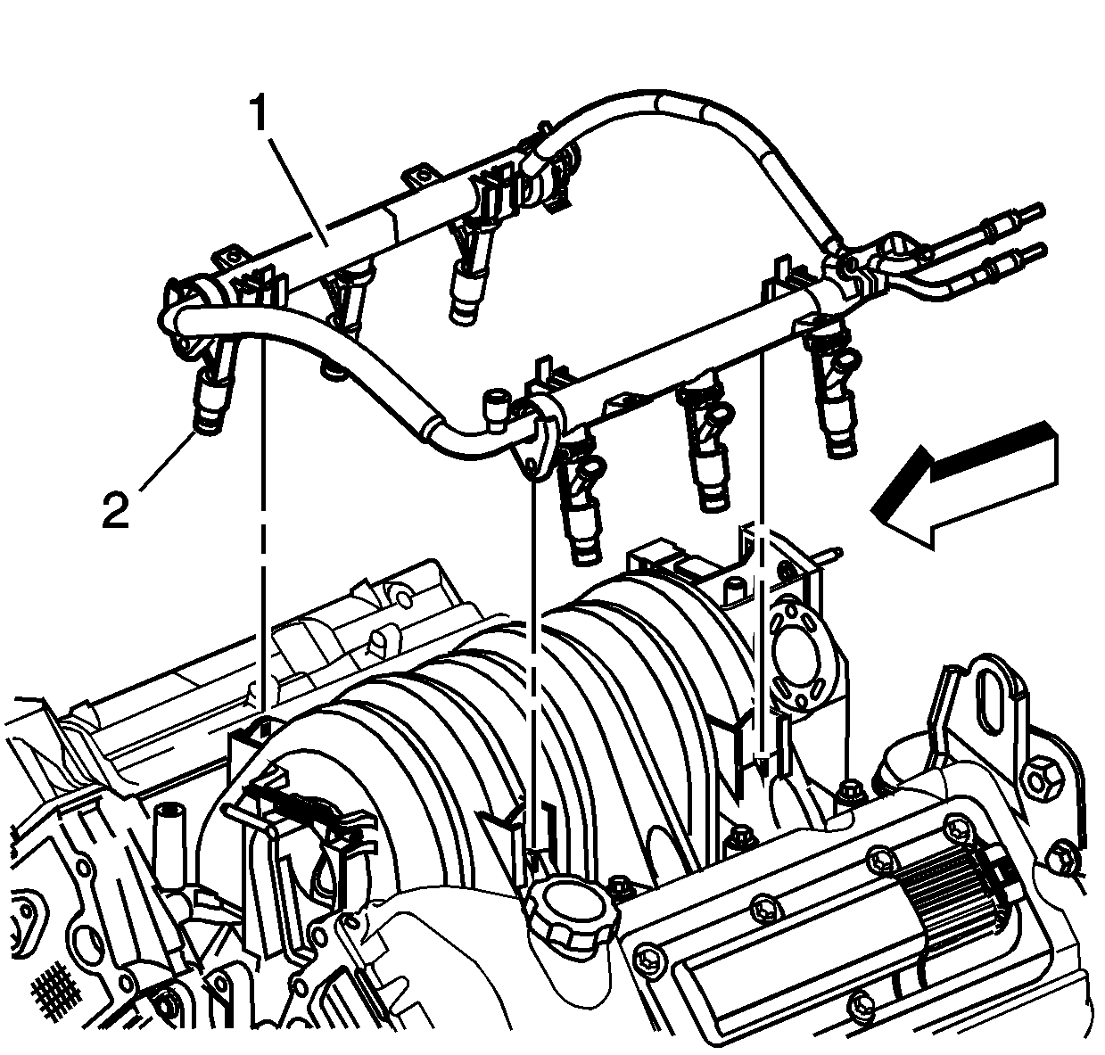
- Inspect the fuel injector
O-rings (2) for misalignment or damage. Replace the O-rings if necessary.
Important: Do not apply excessive pressure to the fuel rail when installing. If
excessive pressure is needed to install the fuel rail then misalignment of
a fuel injector could be the concern and using excessive pressure
will only cause damage to the seal or intake manifold.
- Install the fuel rail (1) and fuel injectors (2) by aligning the
fuel injectors with their respective ports and pressing the four fuel rail
snap-lock connectors into the intake manifold until they lock
in place.
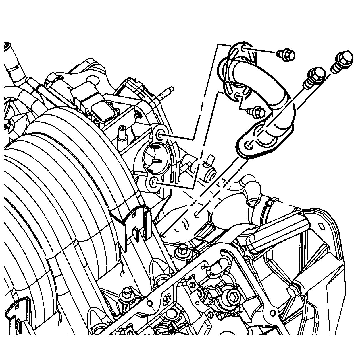
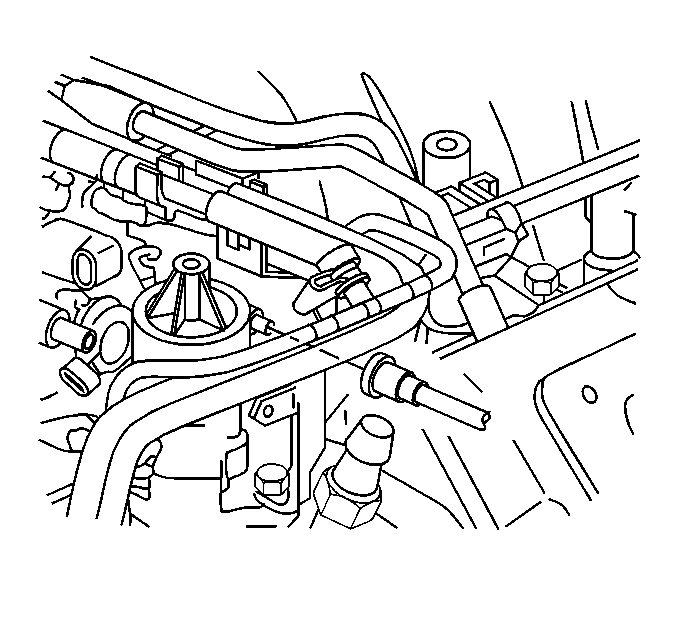
- Install the EGR outlet
pipe.
- Install the EGR outlet pipe to intake manifold bolt.
Tighten
Tighten the EGR outlet pipe to intake manifold bolt to 10 N·m
(89 lb in).
- Install the EGR outlet pipe to water crossover bolt.
Tighten
Tighten the EGR outlet pipe to water crossover bolt to 24 N·m
(18 lb ft).
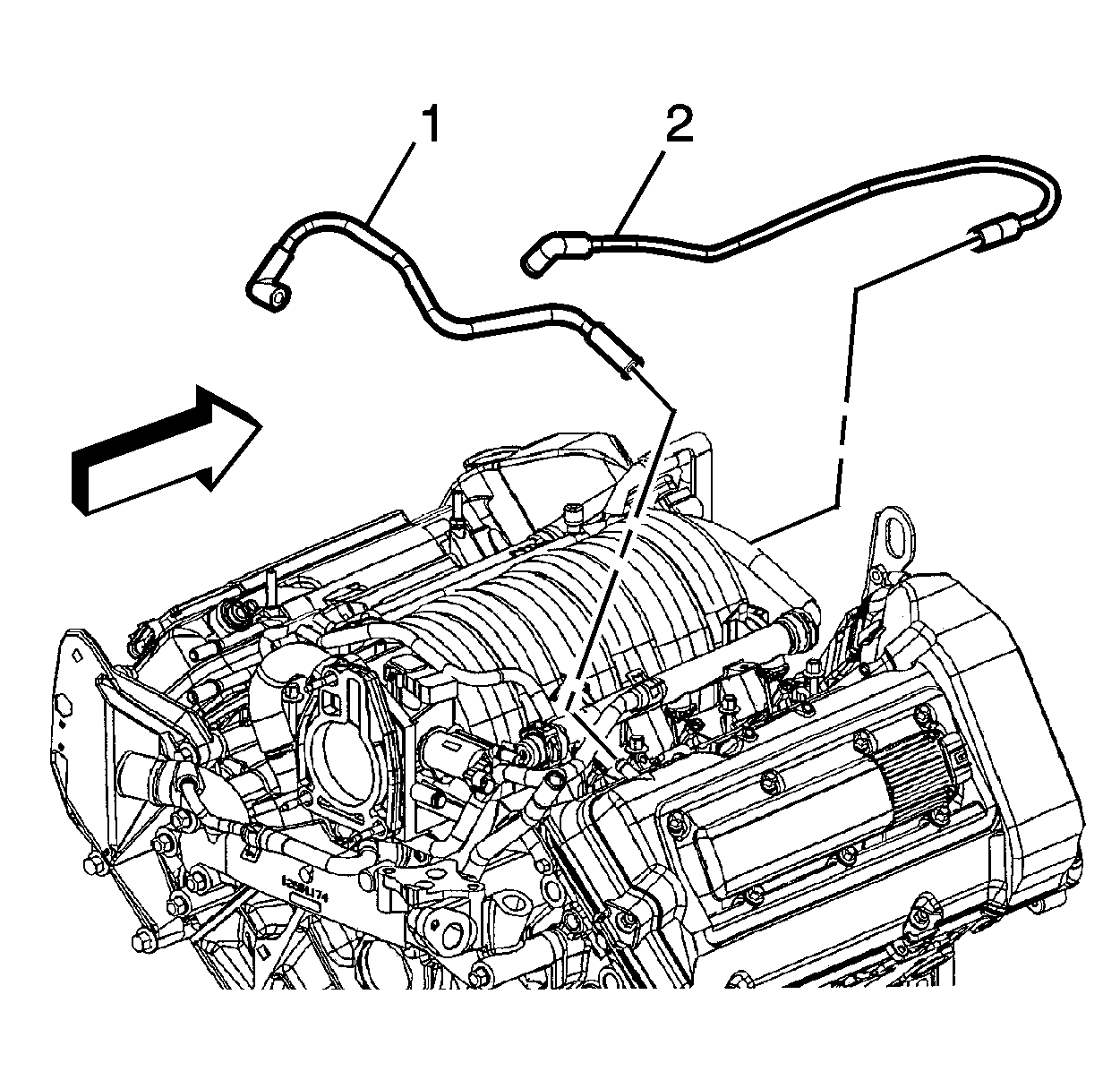
- Install the PCV valve
and connect both feed tubes (1, 2) to the camshaft covers and intake
manifold.
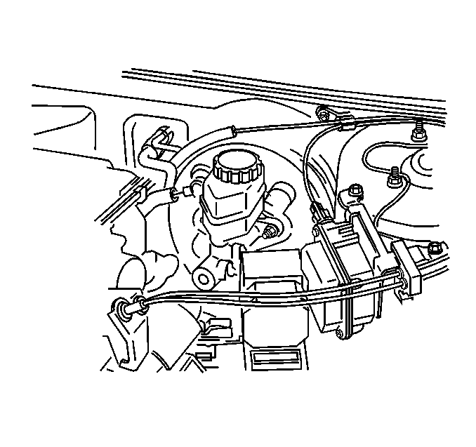
- Install the brake booster
vacuum hose to the brake booster.
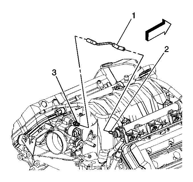
- Install the fuel pressure
regulator vacuum tube (1) to the regulator (2) and the throttle
body (3).
- Install the A/C vacuum hose to the intake manifold.
- Install the engine wiring harness and channel.
- Install the engine wiring harness channel bolts to the camshaft
covers.
Tighten
Tighten the engine wiring harness channel bolts to 10 N·m
(89 lb in).
- Connect the surge tank inlet pipe retainer to the fuel injector
rail.
- Connect the engine wiring harness connectors to the following
components:
| • | Throttle position (TP) sensor |
| • | Idle air control (IAC) valve |
| • | EVAP canister purge solenoid |
| • | Manifold absolute pressure (MAP) sensor |
- Connect the throttle body coolant hoses to the throttle body.
Refer to
Throttle Body Heater Inlet Hose Replacement
and
Throttle Body Heater Outlet Hose Replacement
in Engine Cooling.
- Connect the throttle and cruise control cables with the mounting
bracket to the throttle body. Refer to the following procedures:
- Connect the fuel lines
to the fuel rail. Refer to
Metal Collar Quick Connect Fitting Service
or
Plastic Collar Quick Connect Fitting Service
in Engine Controls-3.5L.
- Connect the fuel vapor
line to the EVAP canister purge solenoid.
- Install the fuel injector sight shield. Refer to
Fuel Injector Sight Shield Replacement
.
- Install the throttle body air inlet duct to the throttle body.
Refer to
Air Cleaner Inlet Duct Replacement
in Engine Controls-3.5L.
- Fill the cooling system with engine coolant. Refer to
Cooling System Draining and Filling
in Engine
Cooling.
- Connect the battery ground (negative) cable. Refer to
Battery Negative Cable Disconnection and Connection
in Engine Electrical.
