Fuel Injector Replacement Right
Tools Required
| • | EN-47909 Injector Bore and Sleeve Cleaning Kit |
| • | J-46594 Fuel Injector Puller |
Removal Procedure
- Remove the upper right valve cover. Refer to Valve Rocker Arm Cover Replacement - Upper Right Side .
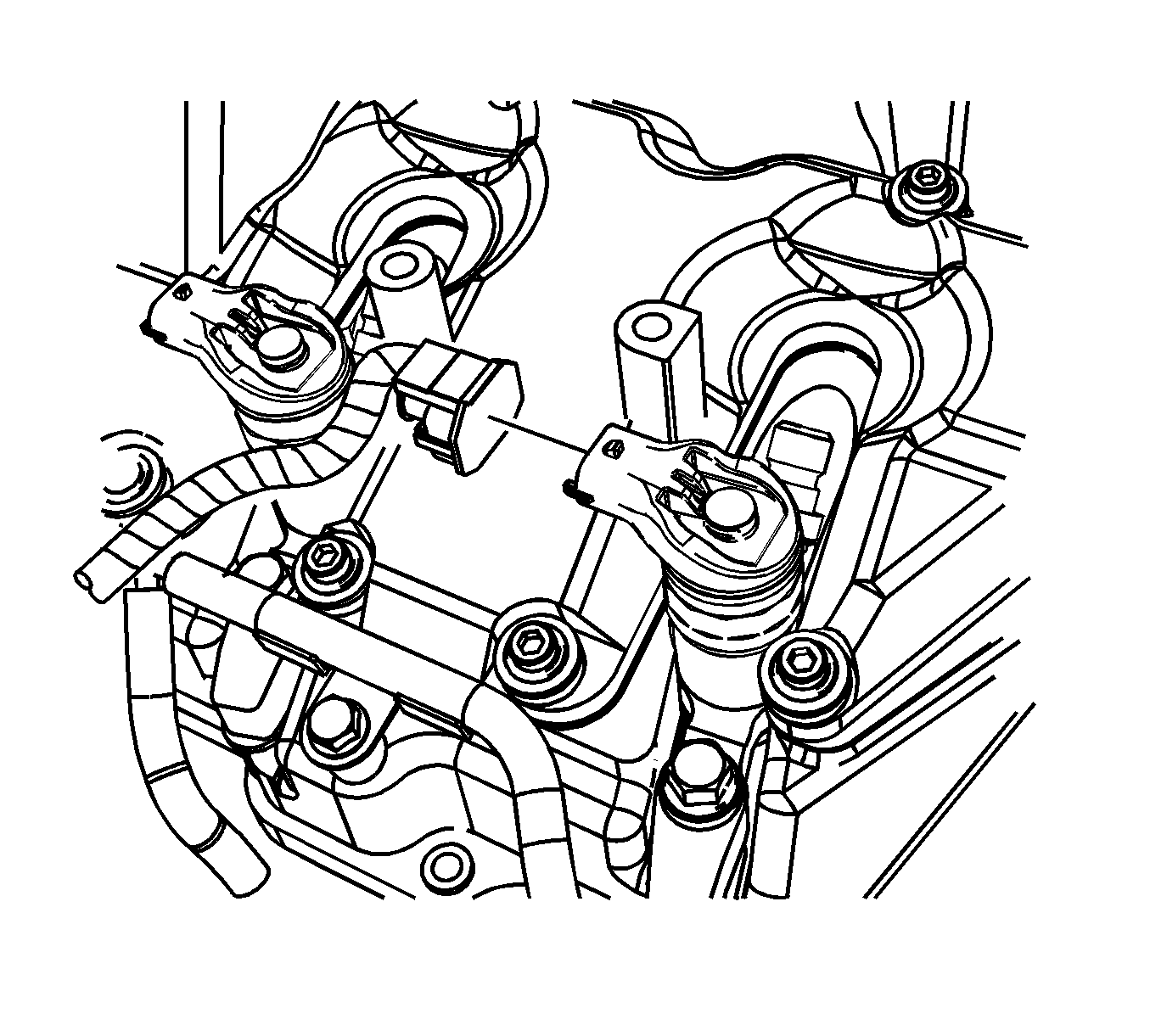
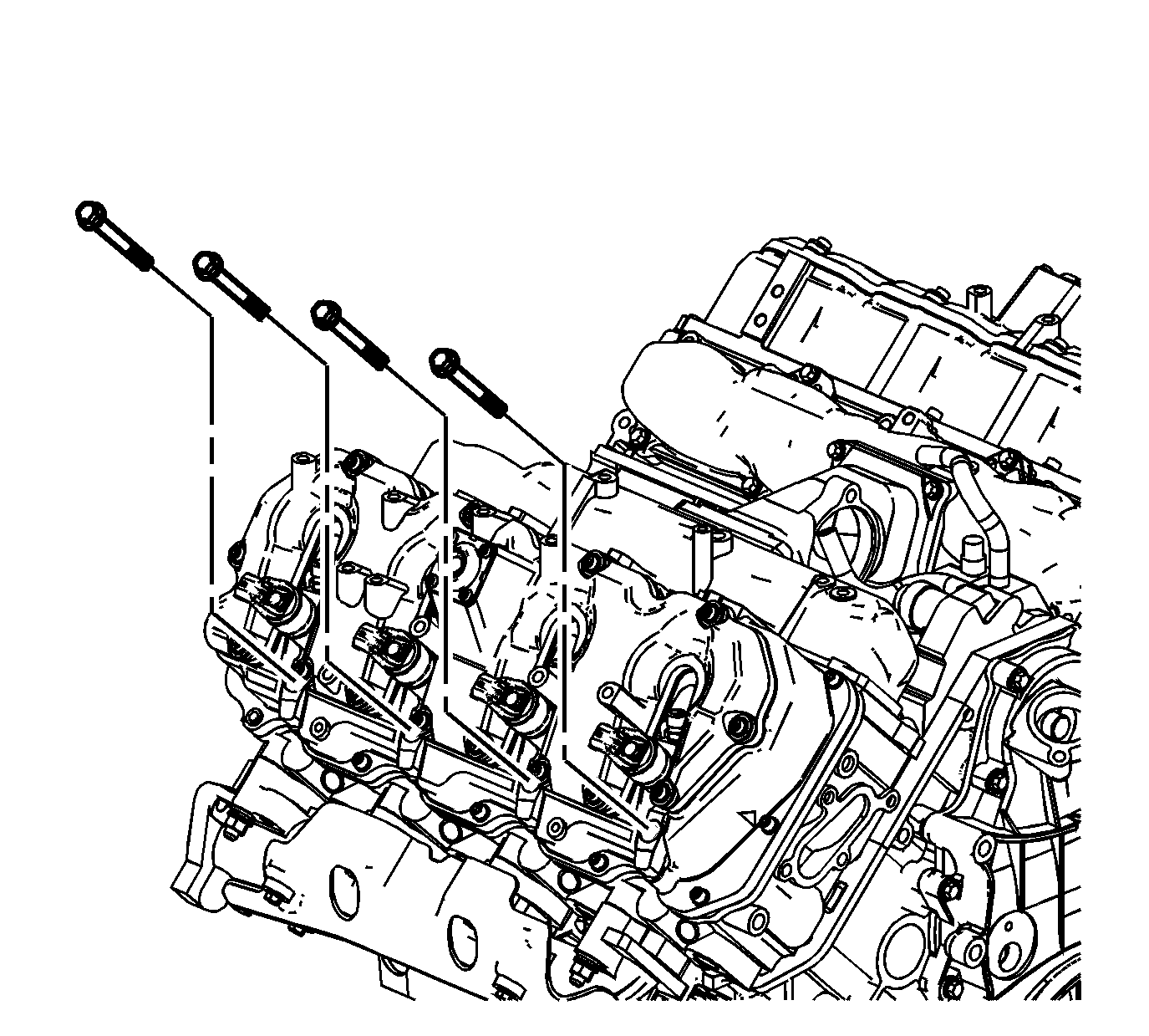
- Remove the fuel injector bracket bolts.
- Install J-46594 into the bolt hole in the fuel injector bracket.
- Install a flare nut wrench onto J-46594 and pull back away from the fuel injector, until the injector releases from its seat.
- Remove the J-46594 .
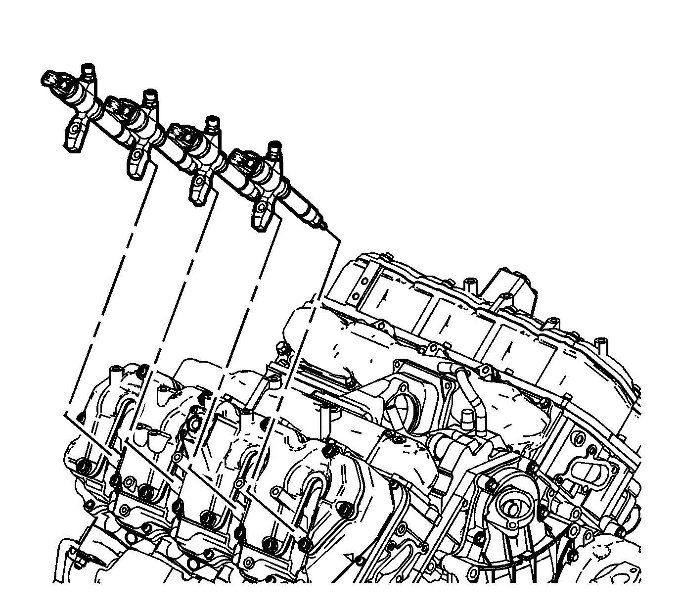
- Remove the fuel injectors with brackets.
- Remove and discard the copper washer from the fuel injector bore.
- Remove and discard the fuel injector O-ring from the injector.
Fuel Injector Cleaning and Inspection
Important: If reusing the old injectors perform the following:
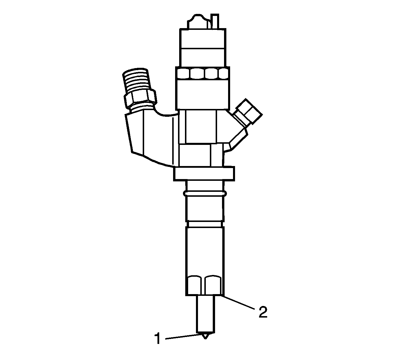
- Use a soft bristle non-metallic brush and Top Engine Cleaner, GM P/N 1052626 or equivalent, to remove any deposits from the nozzle tip (1) and the copper washer sealing area (2) before re-installation.
- Inspect the fuel injector nozzle tip (1) for any signs of discoloration (dark yellow, tan or blue) due to excessive heat.
- Replace the injector if any damage is found.
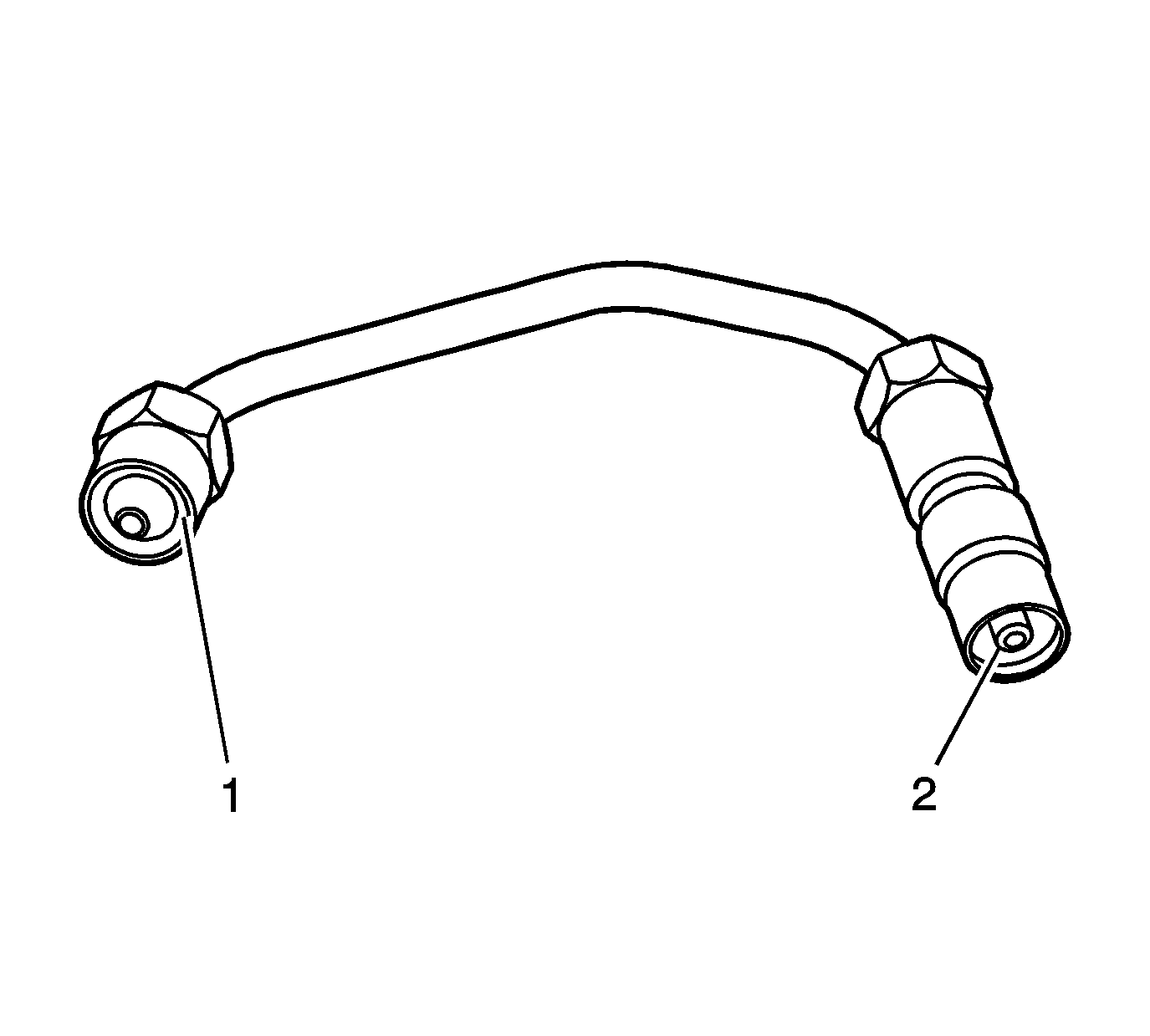
- Clean the fuel injector high pressure line.
- Inspect the fuel injector line for excessive corrosion or damage to the sealing surfaces (1, 2). Replace the line if any damage is found.
Injector Bore Cleaning
Important: The procedure below will aid in the cleaning of carbon deposits from the injector sleeve during an injector replacement.
- Install the EN-47909-2 Radial Brush (brass), to the EN-47909-1 Handle Assembly.
- Insert the brush into the injector bore and rotate the handle in order to break loose any carbon deposits from the injector bore walls and the combustion deck hole.
- Using compressed air, evacuate any debris from the injector bore.
- Remove the radial brush from the handle assembly.
- Install the EN-47909-3 Axial Brush (nylon), to the EN-47909-1.
- Insert the axial brush into the injector bore and rotate the handle while also applying a slight downward pressure, in order to force the brush ends into the bottom corners of the injector bore.
- Using compressed air, evacuate any debris from the injector bore.
- Lightly dampen EN-47909-20 Cotton Swab with Top Engine Cleaner, GM P/N 1052626 (Canadian P/N 993026) or equivalent, and wipe away any deposits from the injector bore.
- Inspect the injector bore for any deposits and repeat brushing if necessary.
- If necessary, crank the engine in order to expel any solvent before starting the engine.
Caution: Wear safety glasses in order to avoid eye damage.
Caution: Wear safety glasses in order to avoid eye damage.
Notice: Do not allow excessive amounts of solvent to go into the cylinder during cleaning. Failure to do so may cause engine damage upon startup.
Caution: Keep hands and face clear of glow plug holes while cranking. Hot liquid or gases may be expelled during cranking.
Caution: Wear safety glasses in order to avoid eye damage.
| 10.1. | Remove the glow plugs. Refer to Glow Plug Replacement - Bank 1 and/or Glow Plug Replacement - Bank 2 . |
| 10.2. | Disable the fuel system. |
| 10.3. | Disconnect the crankshaft position (CKP) sensor electrical connector. |
| 10.4. | Crank the engine in order to expel any excessive solvent. |
| 10.5. | Using the cotton swabs supplied with the kit, wipe the injector bore clean of any solvent and/or debris. |
| 10.6. | Connect the CKP sensor electrical connector. |
| 10.7. | Enable the fuel system. |
| 10.8. | Reinstall the glow plugs. Refer to Glow Plug Replacement - Bank 1 and/or Glow Plug Replacement - Bank 2 . |
Installation Procedure
- Install a NEW copper washer to the fuel injector bore.
- Install a NEW fuel injector O-ring to the injector.
- Install the fuel pressure regulator bracket nut and bolt.
- Install the upper right valve cover. Refer to Valve Rocker Arm Cover Replacement - Upper Right Side .
- If the fuel injectors were replaced, refer to Fuel Injector Flow Rate Programming .
- Prime the fuel system. Refer to Fuel System Priming .
- Start the engine. If the engine stalls, repeat the above step.
- Once the engine starts, inspect for fuel leaks.
- Install the engine cover. Refer to Engine Cover Replacement .

Notice: Refer to Fastener Notice in the Preface section.
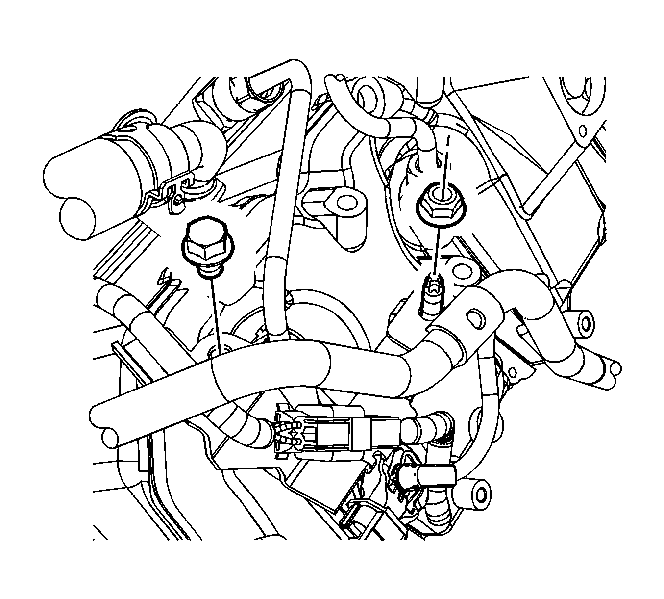
Tighten
Tighten the bracket bolt and nut to 10 N·m (89 lb in).
Fuel Injector Replacement Left
Tools Required
| • | EN-47909 Injector Bore and Sleeve Cleaning Kit |
| • | J-46594 Fuel Injector Puller |
Removal Procedure
- Remove the upper fan shroud. Refer to Engine Coolant Fan Upper Shroud Replacement .
- If equipped, remove the auxiliary generator. Refer to Auxiliary Generator Replacement .
- Remove the glow plug module and bracket. Refer to Glow Plug Control Module Replacement .
- Remove the injector/glow plug wire harness retaining bolt at lower upper valve cover.
- Remove the fuel feed/return line bracket and bolt located under the glow plug mount bracket.
- Disconnect the left engine wiring harness connector.
- Remove the engine wiring harness to bracket bolt, the 2 engine wiring harness bracket to upper valve cover bolts and remove the bracket (1).
- Remove the left fuel injector pipes.
- Remove the fuel return hose clips (1).
- Disconnect the fuel return hose from the injectors.
- Disconnect the fuel injector electrical connectors.
- Remove the fuel injector bracket bolts.
- Install J-46594 into the bolt hole in the fuel injector bracket.
- Install a flare nut wrench onto J-46594 and pull back away from the fuel injector, until the injector releases from its seat.
- Remove J-46594 .
- Remove the fuel injectors with brackets.
- Remove and discard the copper washer from the fuel injector bore.
- Remove and discard the fuel injector O-ring from the injector.
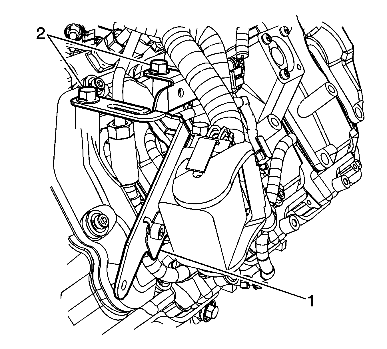
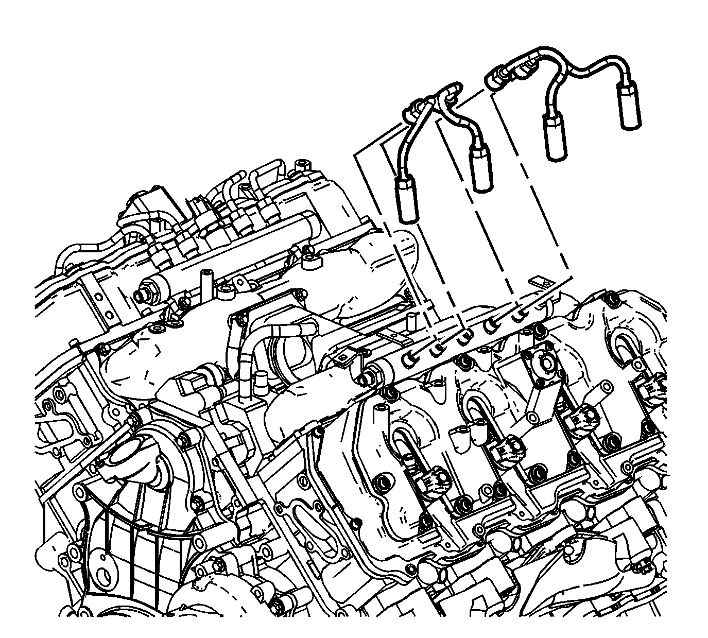
Important:
• Prior to removal of the fuel injector pipes, use compressed air to remove any debris from the injector line and fittings. • Spray lithium grease, GM P/N 12346293 or equivalent, between the fuel injector line and fittings to assist with removal.
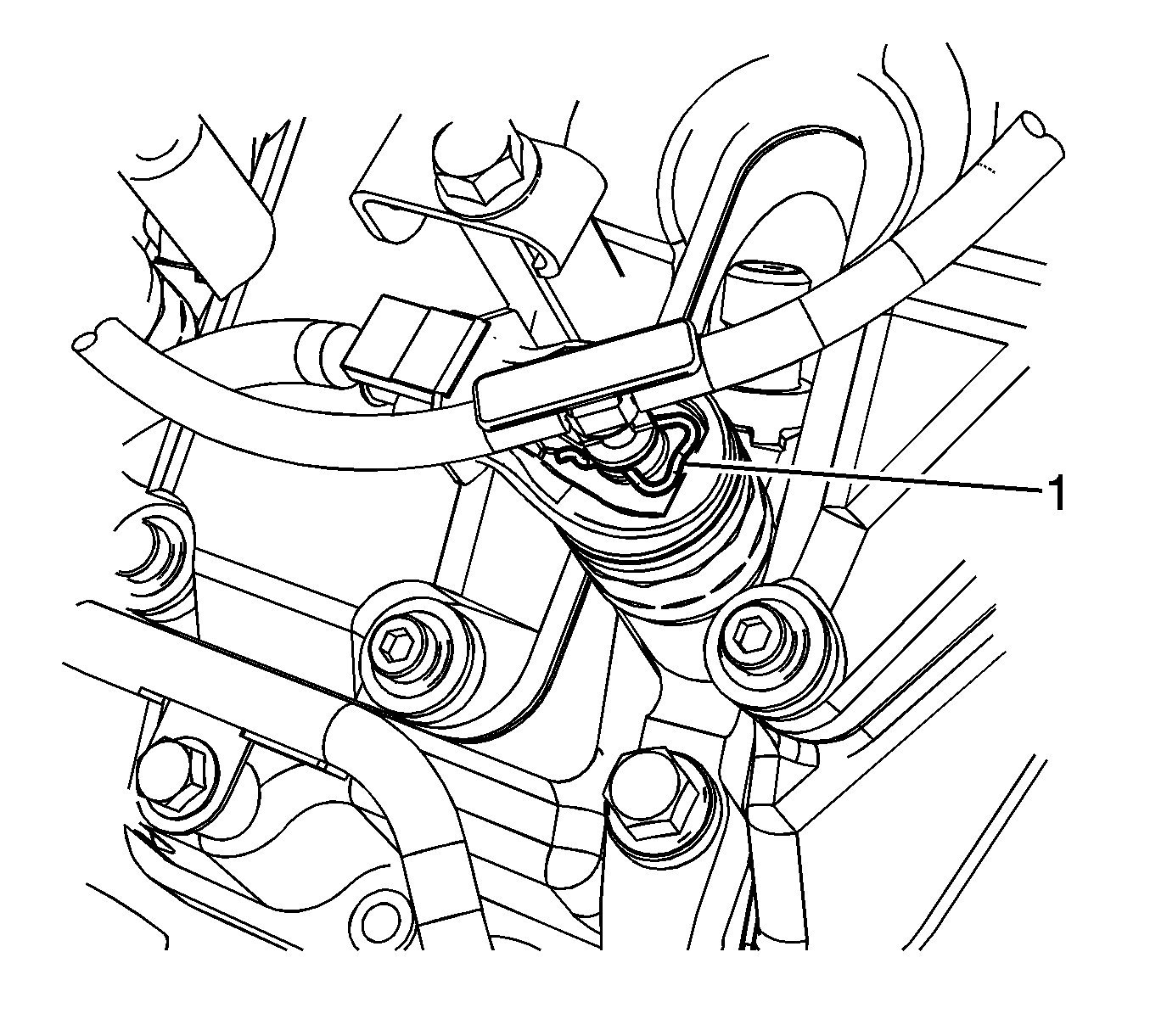
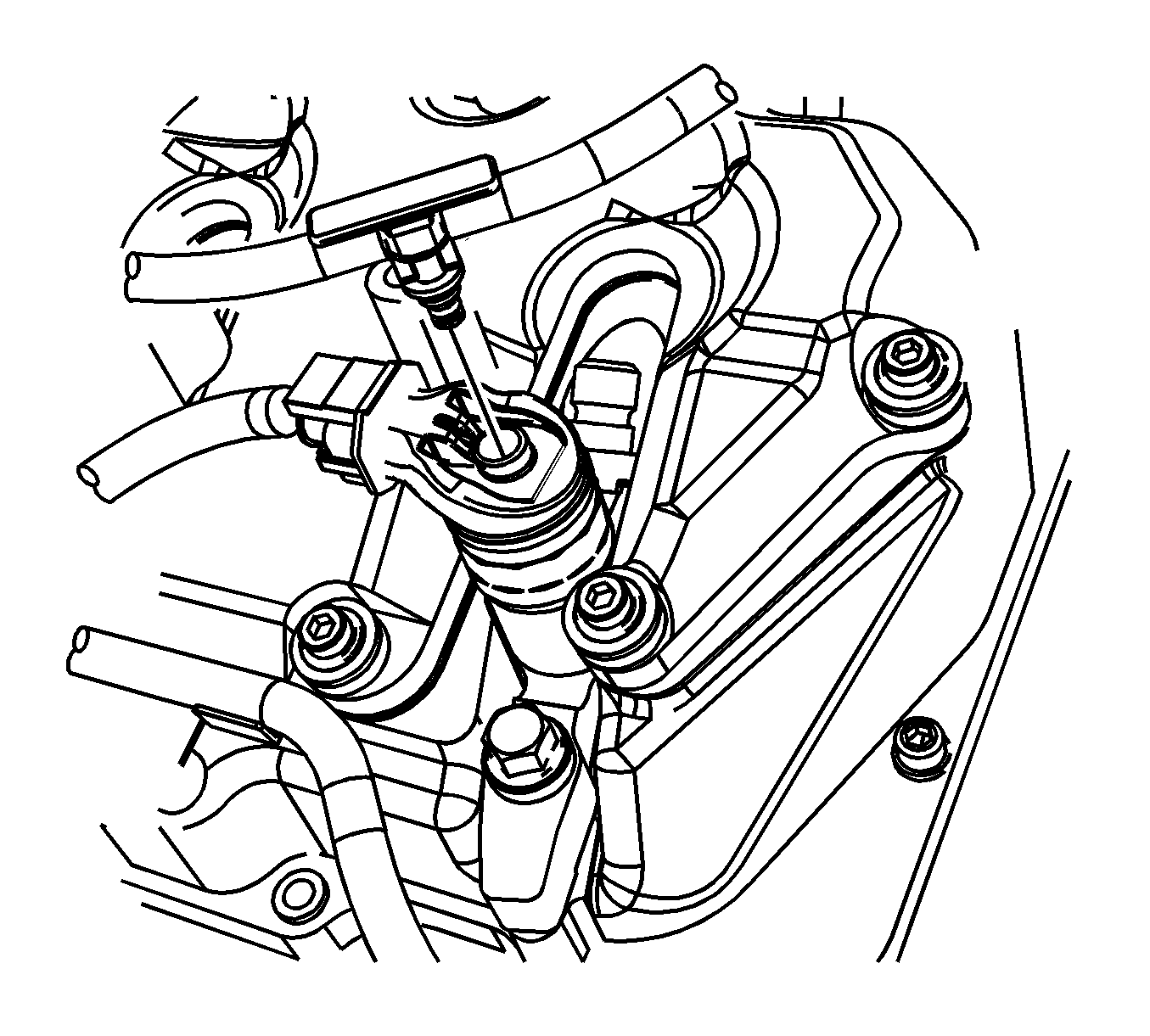

Notice: Label all the injector electrical connectors before the connectors are removed in order to prevent reconnecting to the wrong injector. Failure to properly connect the injectors in the correct sequence will cause severe engine damage.
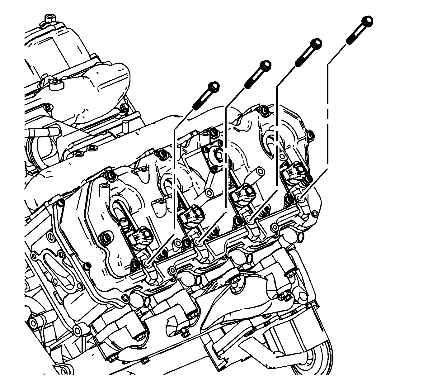
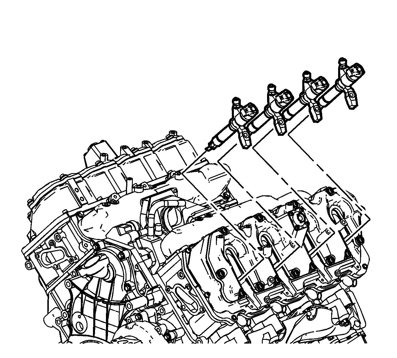
Fuel Injector Cleaning and Inspection
Important: If reusing the old injectors perform the following:
- Use a soft bristle non-metallic brush and Top Engine Cleaner, GM P/N 1052626 or equivalent, to remove any deposits from the nozzle tip (1) and the copper washer sealing area (2) before re-installation.
- Inspect the fuel injector nozzle tip (1) for any signs of discoloration (dark yellow, tan or blue) due to excessive heat.
- Replace the injector if any damage is found.
- Clean the fuel injector high pressure line.
- Inspect the fuel injector line for excessive corrosion or damage to the sealing surfaces (1, 2). Replace the line if any damage is found.


Injector Bore Cleaning
Important: The procedure below will aid in the cleaning of carbon deposits from the injector sleeve during an injector replacement.
- Install the EN-47909-2 Radial Brush (brass), to the EN-47909-1 Handle Assembly.
- Insert the brush into the injector bore and rotate the handle in order to break loose any carbon deposits from the injector bore walls and the combustion deck hole.
- Using compressed air, evacuate any debris from the injector bore.
- Remove the radial brush from the handle assembly.
- Install the EN-47909-3 Axial Brush (nylon), to the EN-47909-1.
- Insert the axial brush into the injector bore and rotate the handle while also applying a slight downward pressure, in order to force the brush ends into the bottom corners of the injector bore.
- Using compressed air, evacuate any debris from the injector bore.
- Lightly dampen EN-47909-20 Cotton Swab with Top Engine Cleaner, GM P/N 1052626 (Canadian P/N 993026) or equivalent, and wipe away any deposits from the injector bore.
- Inspect the injector bore for any deposits and repeat brushing if necessary.
- If necessary, crank the engine in order to expel any solvent before starting the engine.
Caution: Wear safety glasses in order to avoid eye damage.
Caution: Wear safety glasses in order to avoid eye damage.
Notice: Do not allow excessive amounts of solvent to go into the cylinder during cleaning. Failure to do so may cause engine damage upon startup.
Caution: Keep hands and face clear of glow plug holes while cranking. Hot liquid or gases may be expelled during cranking.
Caution: Wear safety glasses in order to avoid eye damage.
| 10.1. | Remove the glow plugs. Refer to Glow Plug Replacement - Bank 1 and/or Glow Plug Replacement - Bank 2 . |
| 10.2. | Disable the fuel system. |
| 10.3. | Disconnect the crankshaft position (CKP) sensor electrical connector. |
| 10.4. | Crank the engine in order to expel any excessive solvent. |
| 10.5. | Using the cotton swabs supplied with the kit, wipe the injector bore clean of any solvent and/or debris. |
| 10.6. | Connect the CKP sensor electrical connector. |
| 10.7. | Enable the fuel system. |
| 10.8. | Reinstall the glow plugs. Refer to Glow Plug Replacement - Bank 1 and/or Glow Plug Replacement - Bank 2 . |
Installation Procedure
- Install a NEW copper washer to the fuel injector bore.
- Install a NEW fuel injector O-ring to the injector.
- Install the fuel injectors with brackets.
- Install the fuel injector bracket bolts.
- Connect the fuel injector electrical connectors.
- Connect the fuel return hose to the injectors.
- Install the fuel return hose clips (1).
- Install the left fuel injector pipes.
- After installing the fuel injector pipes, clean the injector pipes and apply sealant GM P/N 97720043, at the fittings to prevent moisture and debris from collecting between the line and fitting.
- Position the engine wiring harness bracket (1), install the engine wiring harness to bracket bolt and the 2 engine wiring harness bracket to upper valve cover bolts.
- Connect the left engine wiring main harness connector.
- Install the fuel feed/return line bracket and bolt located under glow plug module bracket.
- Install the injector/glow plug wire harness retaining bolt at the lower part of the upper valve cover.
- Install the glow plug module and bracket. Refer to Glow Plug Control Module Replacement .
- If equipped, install the auxiliary generator. Refer to Auxiliary Generator Replacement .
- Install the upper fan shroud. Refer to Engine Coolant Fan Upper Shroud Replacement .
- If the fuel injectors were replaced, refer to Fuel Injector Flow Rate Programming .
- Prime the fuel system. Refer to Fuel System Priming .
- Start the engine. If the engine stalls, repeat the above step.
- Once the engine starts, inspect for fuel leaks.

Notice: Refer to Fastener Notice in the Preface section.

Tighten
Tighten the fuel injector bracket bolts to 30 N·m (22 lb ft).


Notice: Ensure proper torquing of the fuel injector line. An under-torqued fuel injector line will not seal properly and an over-torqued fuel injector line may damage the fuel injector fitting. An improperly sealed or damaged fuel injector line or fuel injector fitting will cause a fuel leak.
Tighten
Tighten the fuel injector pipes to 41 N·m (30 lb ft).

Tighten
Tighten the bolts to 21 N·m (15 lb ft).
