GM Service Manual Online
For 1990-2009 cars only
Table 1: Injector Balance Test Example
Table 2: Engine Coolant Temperature - ECT Within 10°C - 35°C (50°F - 95°F) Test Procedure

Object Number: 17713  Size: SF
(1)First Reading
(2)Second Reading

Injector Balance Test Example

Cylinder (s)

1

2

3

4

5 and 6

7 and 8

1st Reading

333 kPa (48 psi)

333 kPa (48 psi)

333 kPa (48psi)

333 kPa (48psi)

333 kPa (48 psi)

333 kPa (48 psi)

2nd Reading

166 kPa (24psi)

151 kPa (22 psi)

159 kPa (23 psi)

179 kPa (26 psi)

166 kPa (24 psi)

166 kPa (24 psi)

Amount of Drop

166 kPa (24 psi)

179 kPa (26 psi)

172 kPa (25 psi)

151 kPa (22 psi)

166 kPa (24 psi)

166 kPa (24 psi)

Average Range: 156-176 kPa (22.5-25.5 psi)

Injector OK

Faulty injector - too much fuel drop

Injector OK

Faulty injector - too little fuel drop

Injector OK

Injector OK

Circuit Description

The Fuel Injector Balance Test compares the performance of each of the cylinder by using the PCM to shut off fuel injection. The J 39021 Fuel Injector Tester is being used to energize the fuel injector for a precise time period. This measures the performance of each cylinder by the amount of RPM drop caused by that cylinder not producing a power stroke. If proper fuel delivery has been determined, then a cylinder that does not show good performance (RPM drop) indicates either an ignition or mechanical problem.

Diagnostic Aids

Any fuel injector that significantly (more than 10 kPa) requires service.

Test Description

Caution: Wrap a shop towel around the fuel pressure connection in order to reduce the risk of fire and personal injury. The towel will absorb any fuel leakage that occurs during the connection of the fuel pressure gage. Place the towel in an approved container when the connection of the fuel pressure gage is complete.

  1. The engine coolant temperature affects the ability of the fuel injector tester to detect a faulty fuel injector. If the engine coolant temperature is NOT between 10°C and 35°C (50°F and 95°F), go to Fuel Injector Solenoid Coil Test - Engine Coolant Temperature Outside 10-35 Degrees C (50-95 Degrees F) .

  2. The first second of the voltage displayed by the DMM may be inaccurate due to the initial current surge, therefore, record the lowest voltage displayed by the DMM after the first second of the test. The voltage displayed by the DMM should be within the specified range (refer to the Example). The voltage displayed by the DMM may increase throughout the test as the fuel injector windings warm and the resistance of the fuel injector windings changes. An erratic voltage reading (large fluctuations in voltage that do not stabilize) indicates an intermittent connection within the fuel injector.

Resistance Ohms

Voltage Specification at 10°C-35°C

(50°F-95°F)

11.4-12.6

5.7-6.6

Fuel Injector Number

Voltage Reading

Pass/Fail

1

6.3

P

2

5.9

P

3

6.2

P

4

6.1

P

5

4.8

F

6

6.0

P

7

6.1

P

8

5.8

P

Engine Coolant Temperature - ECT Within 10°C - 35°C (50°F - 95°F) Test Procedure

Step

Action

Value(s)

Yes

No

1

Was the Powertrain On-Board Diagnostic (OBD) System Check performed?

--

Go to Step 2

Go to Powertrain On Board Diagnostic (OBD) System Check

2

  1. Connect the scan tool.
  2. Check the engine coolant temperature.

Is the engine coolant temperature within the specified limits?

10°C-35°C (50°F-95°F)

Go to Step 3

Go to Fuel Injector Solenoid Coil Test - Engine Coolant Temperature Outside 10-35 Degrees C (50-95 Degrees F)

3

  1. Turn the ignition OFF.
  2. Notice: In order to prevent flooding of a single cylinder and possible engine damage, relieve the fuel pressure before performing the fuel injector coil test procedure.

  3. Relieve the fuel pressure. Refer to Fuel Pressure Relief .
  4. Access the fuel injector electrical connectors as required.
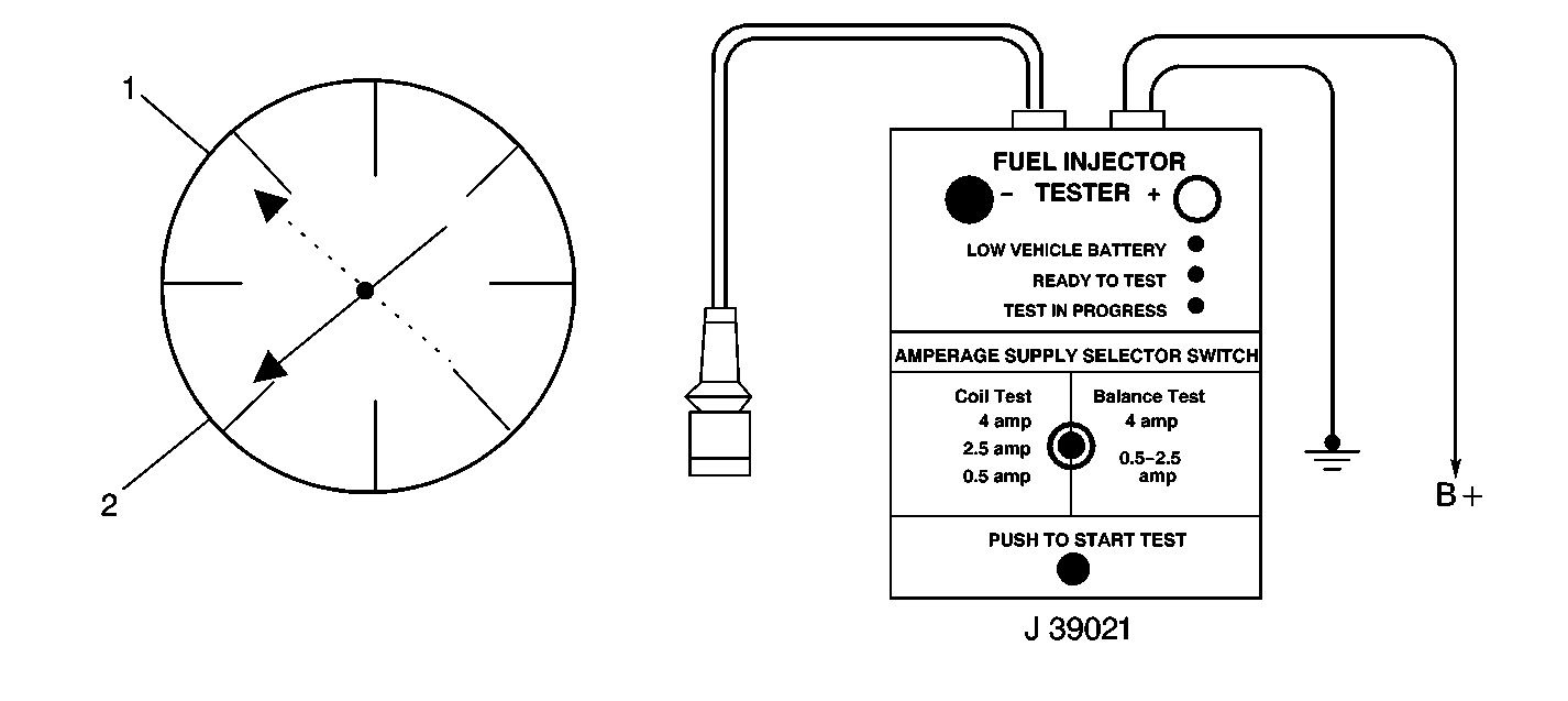
  5. Connect the J 39021 fuel injector tester to B+ and ground.
  6. Set the amperage supply selector switch on the fuel injector tester to the Coil Test 0.5 amp position.
  7. Connect the leads from the J 39200 Digital Multi Meter (DMM) to the fuel injector tester. Refer to Fuel Injector Coil Test illustration.
  8. Set the DMM to the tenths scale (0.0).
  9. Connect the fuel injector tester to a fuel injector.
  10. Important: Check the engine coolant temperature again to ensure that the correct table is being used.

  11. Press the Push to Start Test button on the fuel injector tester.
  12. Important : The voltage reading may rise during the test.

  13. Observe the voltage reading on the DMM.
  14. Record the lowest voltage observed after the first second of the test.
  15. Repeat Steps 8 through 11 for each fuel injector.
  16. Identify the highest voltage reading recorded other than those above 9.5 volts.
  17. Subtract any other voltage reading recorded from the highest voltage reading recorded.
  18. Repeat Step 14 for all of the remaining fuel injectors.

Did any fuel injector have an erratic voltage reading (large fluctuations in voltage that do not stabilize) or a voltage reading outside of the specified limits?

5.7-6.6V

Go to Step 4

Go to Fuel Injector Balance Test

4

Replace the faulty fuel injector(s). Refer to Fuel Injector Replacement .

Is the action complete?

--

Go to Fuel Injector Balance Test

--