Intake Manifold Replacement Upper
Removal Procedure
Important: The fuel injector wiring harness connectors must be connected to their respective fuel injectors. Failure to connect the fuel injector connectors to their respective fuel injectors may result in excessive exhaust emissions and poor engine performance.
- Drain the engine coolant from the cooling system. Refer to
Cooling System Draining and Filling
in Engine Cooling.
- Remove the throttle body air inlet duct. Refer to
Air Filter Element Replacement
in Engine Controls.
- Remove the accelerator control and cruise control cables with bracket from the throttle body. Refer to
Accelerator Control Cable Replacement
in Engine Controls.
- Disconnect the wiring harness connectors from the following throttle body components:
| • | Throttle Position (TP) sensor |
| • | Idle Air Control (IAC) valve |
- Disconnect the engine left side spark plug wires. Refer to
Spark Plug Wire Harness Replacement
in Engine Electrical.
- Disconnect the engine left side spark plug wire harness attachment clip. Refer to
Spark Plug Wire Harness Replacement
in Engine Electrical.
- Disconnect the throttle body heater hoses. Refer to
Throttle Body Heater Inlet Hose Replacement
and
Throttle Body Heater Outlet Hose Replacement
in Engine Cooling.
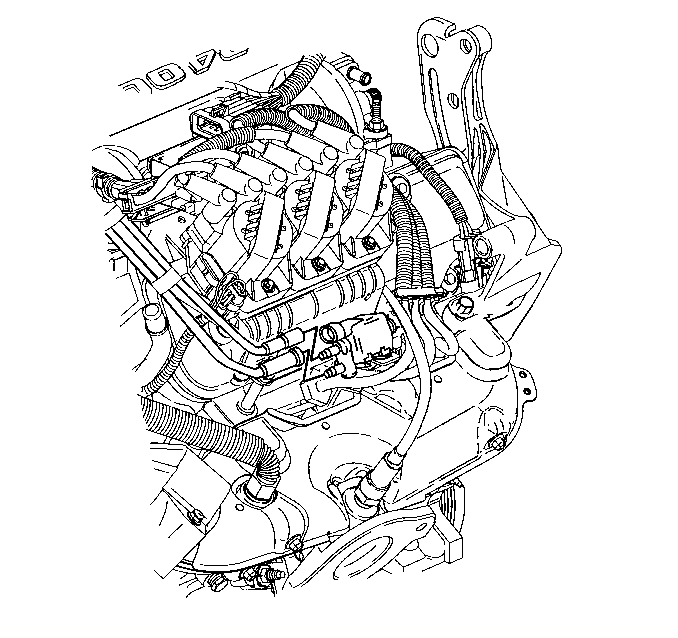
- Disconnect the vacuum hoses from the evaporative emission (EVAP) canister purge solenoid valve.
- Remove the EVAP canister purge solenoid valve. Refer to
Evaporative Emission Canister Purge Solenoid Valve Replacement
in Engine Controls.
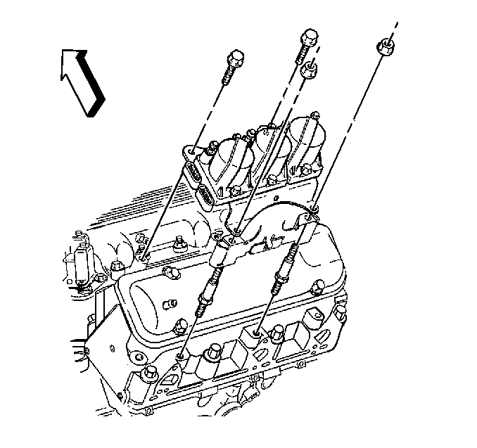
- Remove the ignition coil bracket.
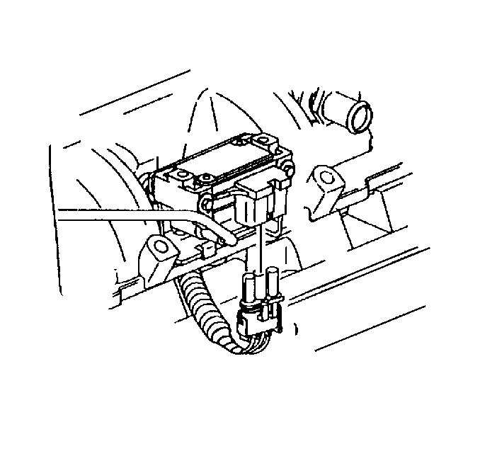
- Disconnect the wiring harness from the manifold air pressure (MAP) sensor.
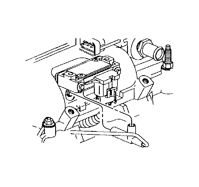
- Disconnect the vacuum harness from the MAP sensor and the upper intake manifold.
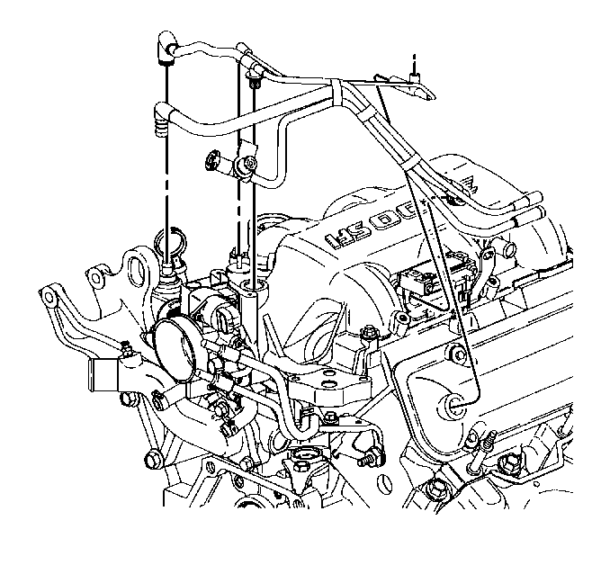
- Disconnect and remove the emission control vacuum harness.
- Disconnect the vacuum brake booster hose from the upper intake manifold. Refer to
Power Vacuum Brake Booster Replacement
in Hydraulic Brakes.
- Disconnect the vacuum hose connections from the upper intake manifold.
| • | Heating, ventilation and air conditioning (HVAC) vacuum source hose |
| • | Fuel pressure regulator |
- Remove the exhaust gas recirculation (EGR) valve. Refer to EGR Valve Replacement in Engine Controls.
- Remove the MAP sensor and the bracket. Refer to
Manifold Absolute Pressure Sensor Replacement
in Engine Controls.
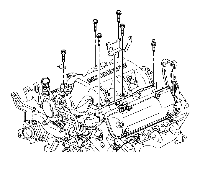
- Remove the upper intake manifold studs and bolts.
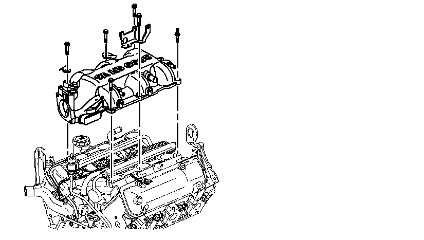
- Remove the upper intake manifold.
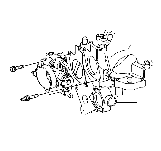
- If you are REPLACING the intake manifold, remove the throttle body. Refer to
Throttle Body Assembly Replacement
in Engine Controls.
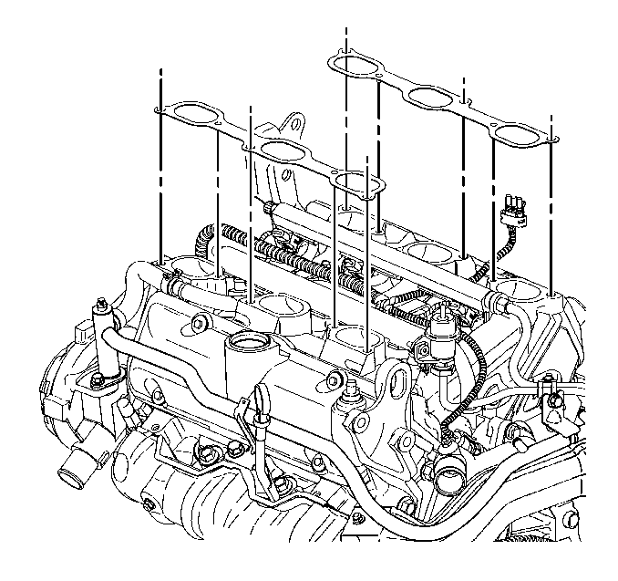
- Remove the upper intake manifold gasket.
- Clean and inspect the upper intake manifold. Refer to
Intake Manifold Cleaning and Inspection
.
Installation Procedure

- If removed, install the throttle body. Refer to
Throttle Body Assembly Replacement
in Engine Controls.

- Install the upper intake manifold gasket.

- Install the upper intake manifold.

- Install the MAP sensor and the bracket. Refer to
Manifold Absolute Pressure Sensor Replacement
in Engine Controls.
- Install the upper intake manifold studs and bolts. Refer to
Intake Manifold Installation
.
- Install the EGR valve. Refer to EGR Valve Replacement in Engine Controls.
- Connect the vacuum hose connections to the upper intake manifold.
| • | Heater and air conditioning vacuum source hose |
| • | Fuel pressure regulator |
- Connect the vacuum brake booster hose to the upper intake manifold. Refer to
Power Vacuum Brake Booster Replacement
in Hydraulic Brakes.
- Install the MAP sensor and the bracket. Refer to
Manifold Absolute Pressure Sensor Replacement
in Engine Controls.

- Install and connect the emission control vacuum harness.

- Connect the vacuum hose to the MAP sensor and the upper intake manifold.

- Connect the wiring harness to the MAP sensor.

- Install the ignition coil bracket with the coils.
- Install the EVAP canister purge solenoid valve. Refer to
Evaporative Emission Canister Purge Solenoid Valve Replacement
in Engine Controls.

- Connect the vacuum hoses to the EVAP canister purge solenoid valve.
- Connect the throttle body heater hoses. Refer to
Throttle Body Heater Inlet Hose Replacement
and
Throttle Body Heater Outlet Hose Replacement
in Engine Cooling.
- Connect the engine left side spark plug wire harness attachment clip. Refer to
Spark Plug Wire Harness Replacement
in Engine Electrical.
- Connect the engine left side spark plug wires. Refer to
Spark Plug Wire Harness Replacement
in Engine Electrical.
- Connect the wiring harness connectors to the throttle body. Refer to
Throttle Body Assembly Replacement
in Engine Controls.
- Install the accelerator control and cruise control cables with bracket to the throttle body. Refer to
Accelerator Control Cable Replacement
in Engine Controls.
- Install the throttle body air inlet duct. Refer to
Air Filter Element Replacement
in Engine Controls.
- Fill the cooling system with engine coolant. Refer to
Cooling System Draining and Filling
in Engine Cooling.
Intake Manifold Replacement Lower
Removal Procedure
Important: The fuel injector wiring harness connectors must be connected to their respective fuel injectors. Failure to connect the fuel injector connectors to their respective fuel injectors may result in excessive exhaust emissions and poor engine performance.
- Remove the upper intake manifold. Refer to
Intake Manifold Replacement
.
- Remove the engine left side valve rocker arm cover. Refer to
Valve Rocker Arm Cover Replacement
.
- Remove the engine right side valve rocker arm cover. Refer to
Valve Rocker Arm Cover Replacement
.
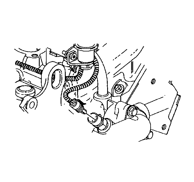
- Disconnect the wiring harness from the engine coolant temperature (ECT) sensor.
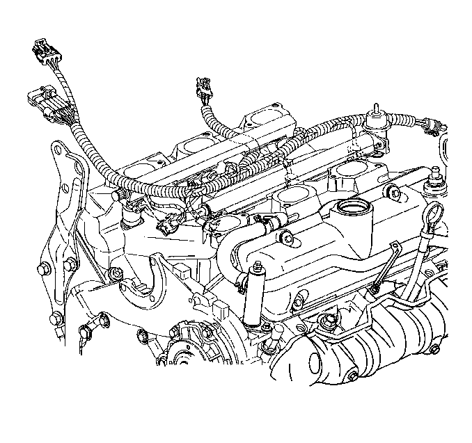
Important: Use masking tape or another appropriate method in order to identify each fuel injector wiring harness connector cylinder number.
- Disconnect and remove the fuel injector, manifold air pressure (MAP) and ECT wiring harness.
- Remove the fuel feed and return pipe from the fuel injector rail. Refer to
Fuel Hose/Pipes Replacement - Engine Compartment
in Engine Controls.
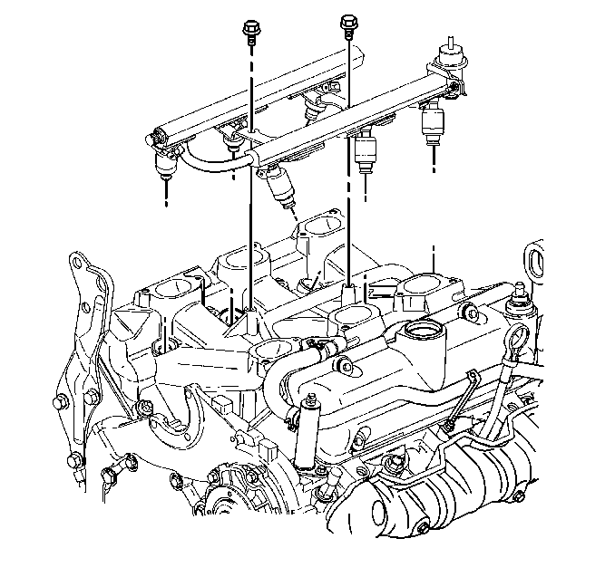
- Remove the fuel injector rail. Refer to
Fuel Injection Fuel Rail Assembly Replacement
in Engine Controls.
Important: Do NOT disconnect the power steering pipes or hoses from the power steering pump.
- Remove the power steering pump from the front engine cover and reposition aside. Refer to
Power Steering Pump Replacement
in Power Steering System.
- Disconnect the heater inlet pipe with heater hose from the lower intake manifold and reposition aside. Refer to
Heater Inlet Pipe Replacement
in Heating, Ventilation and Air Conditioning.
- Disconnect the inlet radiator hose from the engine. Refer to
Radiator Inlet Hose Replacement
in Engine Cooling.
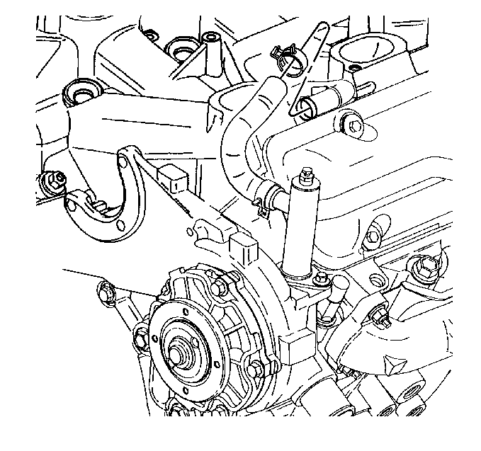
- Disconnect the thermostat bypass hose from the lower intake manifold pipe.
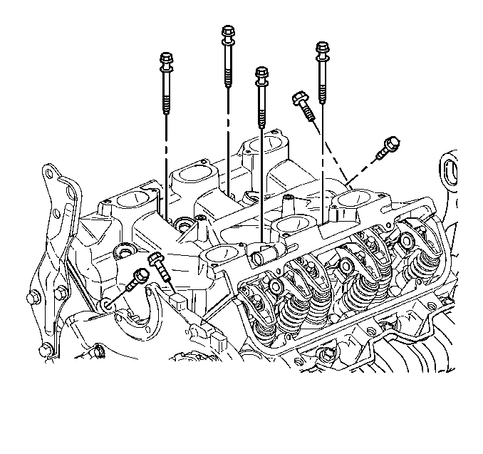
- Remove the lower intake manifold bolts.
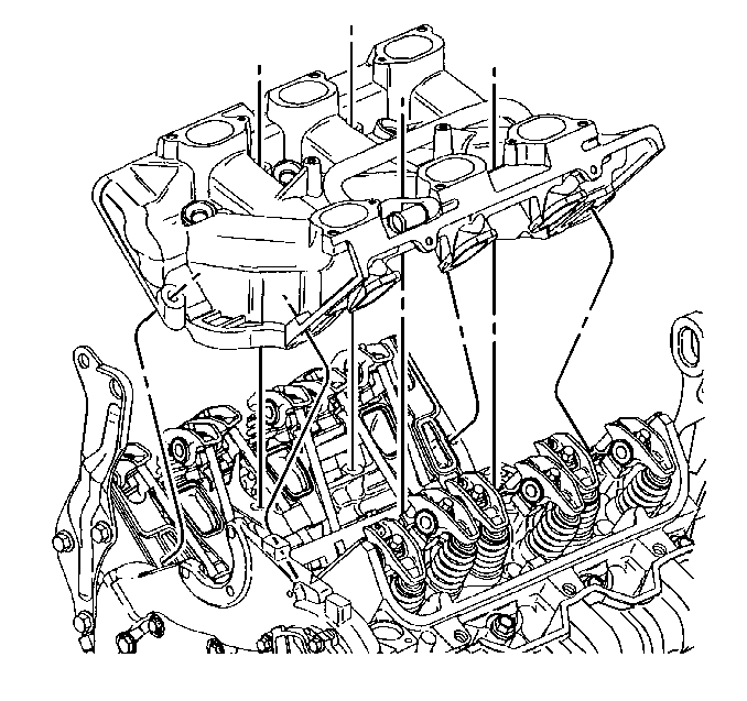
- Remove the lower intake manifold.
- Loosen the valve rocker arms and remove the push rods. Refer to
Valve Rocker Arm and Push Rod Removal
.
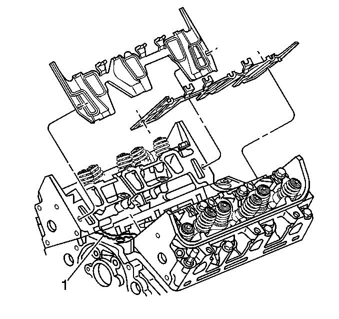
- Remove the lower intake manifold gaskets and seals.
- Clean the lower intake manifold gasket and seal surfaces on the cylinder heads and the engine block.
- Clean and inspect the lower intake manifold. Refer to
Valve Rocker Arm and Push Rod Removal
.
- If you are replacing the lower intake manifold, remove the ECT sensor. Refer to
Engine Coolant Temperature Sensor Replacement
in Engine Controls.
- If you are REPLACING the lower intake manifold, remove the thermostat. Refer to
Engine Coolant Thermostat Replacement
in Engine Cooling.
Installation Procedure
- If removed, install the thermostat and the thermostat housing. Refer to
Engine Coolant Thermostat Replacement
in Engine Cooling.
- If removed, install the ECT sensor. Refer to
Engine Coolant Temperature Sensor Replacement
in Engine Controls.

- Apply 8-12-mm (0.08-0.11-in) bead of RTV Sealer GM P/N 12345739 or equivalent on each ridge where front and rear of the lower intake manifold contact the engine block (1).
- Install the lower intake manifold gaskets.
- Install the push rods and tighten the valve rocker arms. Refer to
Valve Rocker Arm and Push Rod Installation
.

- Install the lower intake manifold. Refer to
Intake Manifold Installation
.

- Install the lower intake manifold bolts.
- Tighten the lower intake manifold bolts. Refer to
Intake Manifold Installation
.

- Connect the thermostat bypass hose to the lower intake manifold pipe.
- Connect the inlet radiator hose from the engine. Refer to
Radiator Inlet Hose Replacement
in Engine Cooling.
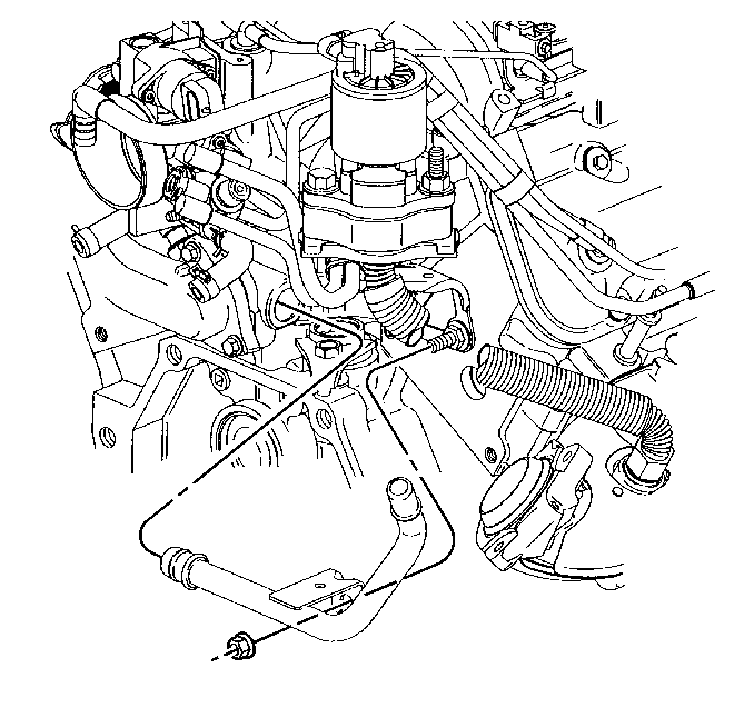
- Connect the heater inlet pipe and heater hose to the lower intake manifold. Refer to
Heater Inlet Pipe Replacement
in Heating, Ventilation and Air Conditioning.
- Install the power steering pump to the front engine cover. Refer to
Power Steering Pump Replacement
in Power Steering System.

- Install the fuel injector rail. Refer to
Fuel Injection Fuel Rail Assembly Replacement
in Engine Controls.
- Connect the fuel feed and return pipe to the fuel injector rail. Refer to
Fuel Hose/Pipes Replacement - Engine Compartment
in Engine Controls.

Important: The fuel injector wiring harness connectors must be connected to their respective fuel injectors. Failure to connect the fuel injector connectors to their respective fuel injectors may result in excessive exhaust emissions and poor engine performance.
- Install and connect the fuel injector, MAP and ECT wiring harness.

- Install the wiring harness to the ECT sensor.
- Install the engine right side valve rocker arm cover. Refer to
Valve Rocker Arm Cover Replacement
.
- Install the engine left side valve rocker arm cover. Refer to
Valve Rocker Arm Cover Replacement
.
- Install the upper intake manifold. Refer to
Intake Manifold Replacement
.


