Refer to
Cell 21: Engine Data Sensors
Circuit Description
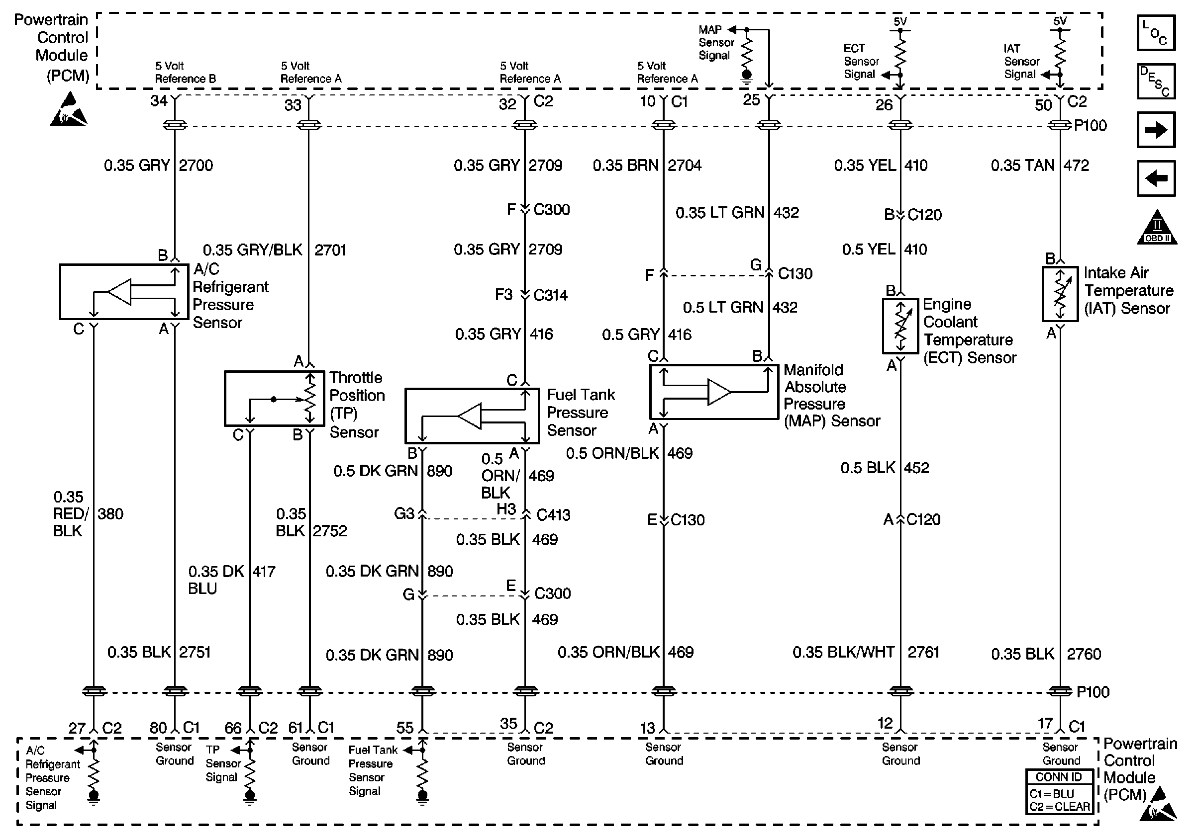
The Throttle Position (TP) sensor circuit provides a voltage signal that changes relative to throttle blade angle. The signal voltage will vary from below 1.0 volts at closed throttle to above 4.0 volts at Wide Open Throttle (WOT).
If the PCM detects an excessively high TP Sensor voltage, DTC P0123 will be set.
Conditions for Setting the DTC
| • | The ignition is on. |
| • | TP sensor signal voltage is greater than 4.88 volts for more than 9.5 seconds |
Action Taken When the DTC Sets
| • | The PCM will illuminate the malfunction indicator lamp (MIL) during the first trip in which the diagnostic runs and fails. |
| • | If equipped with traction control, the PCM will command the EBTCM via the serial data circuit to turn OFF traction control and illuminate the TRACTION OFF lamp. |
| • | The PCM will store conditions which were present when the DTC set as Freeze Frame and Fail Records data. |
Conditions for Clearing the MIL/DTC
| • | The PCM will turn OFF the MIL during the third consecutive trip in which the diagnostic has been run and passed. |
| • | The History DTC will clear after 40 consecutive warm-up cycles have occurred without a malfunction. |
| • | The DTC can be cleared by using the scan tool. |
Diagnostic Aids
Check for the following conditions:
| • | Poor connection at PCM. Inspect harness connectors for backed out terminals, improper mating, broken locks, improperly formed or damaged terminals, and poor terminal to wire connection. Use a corresponding mating terminal to test for proper tension. Refer to Intermittents and Poor Connections Diagnosis Repairing Connector Terminals and Connector Repairs . |
| • | Damaged harness. Inspect the wiring harness for damage. If the harness appears to be OK, observe the TP sensor display on the scan tool while moving connectors and wiring harnesses related to the TP sensor. A change in the display will indicate the location of the fault. Refer to Wiring Repairs . |
| • | Faulty TP sensor: With the key on, engine off, observe the TP sensor display on the scan tool while slowly depressing the accelerator to wide open throttle. If a voltage over 4.90 volts is seen at any point in normal accelerator travel, replace the TP sensor. |
If DTC P0123 cannot be duplicated, the information included in the Fail Records data can be useful in determining vehicle mileage since the DTC was last set. If it is determined that the DTC occurs intermittently, performing the DTC P1121 Throttle Position (TP) Sensor Circuit Intermittent High Voltage diagnostic may isolate the cause of the fault.
Test Description
The numbers below refer to the step numbers on the diagnostic table:
-
Components that share the TP sensor 5 volt reference A circuit include the following devices:
-
This vehicle is equipped with a PCM which utilizes an Electrically Erasable Programmable Read Only Memory (EEPROM). When the PCM is being replaced, the new PCM must be programmed.
| • | The EGR valve |
| • | The engine oil pressure sensor |
| • | The MAP sensor |
| • | Disconnect these components one at a time while observing the TP sensor display on the scan tool. If the reading changes drastically when one of these components is disconnected, replace the component that affected the reading. |
Step | Action | Values | Yes | No |
|---|---|---|---|---|
1 | Was the Powertrain On-Board Diagnostic (OBD) System Check performed? | -- | ||
2 |
Is TP Sensor more than the specified value? | 4.7 V | ||
3 |
Does scan tool indicate DTC P0123 failed? | -- | Go to Diagnostic Aids | |
4 |
Does the scan tool indicate that the TP voltage parameter is equal to the specified value? | 0 V | ||
5 | Using a J 39200 DMM measure the voltage between the 5 volt reference circuit of the TP sensor and a known good ground. Does the voltage measure equal to the specified value? | 5.0 V | ||
6 | Connect a J 35616-200 Test Lamp between the ground circuit of the TP sensor and battery positive voltage. Does the test lamp illuminate? | -- | ||
7 |
Did you find and correct the condition? | -- | ||
8 | Test the signal circuit of the TP sensor for a short to voltage. Refer to Wiring Repairs . Did you find and correct the condition? | -- | ||
Test all 5 volt reference A circuits and connected components for a short to voltage. Refer to Wiring Repairs . Did you find and correct the condition? | -- | |||
10 | Inspect for poor connections at the harness connector of the TP sensor. Refer to Intermittents and Poor Connections Diagnosis and Connector Repairs in Wiring Systems. Did you find and correct the condition? | -- | ||
11 | Inspect for poor connections at the harness connector of the PCM. Refer to Intermittents and Poor Connections Diagnosis and Connector Repairs in Wiring Systems. Did you find and correct the condition? | -- | ||
12 | Replace the TP sensor. Refer to Throttle Position Sensor Replacement . Did you complete the replacement? | -- | -- | |
|
Important: Replacement PCM must be programmed. Replace the PCM. Refer to Powertrain Control Module Replacement/Programming . Did you complete the replacement? | -- | -- | ||
14 |
Does scan tool indicate DTC P0123 failed? | -- | System OK |
