GM Service Manual Online
For 1990-2009 cars only
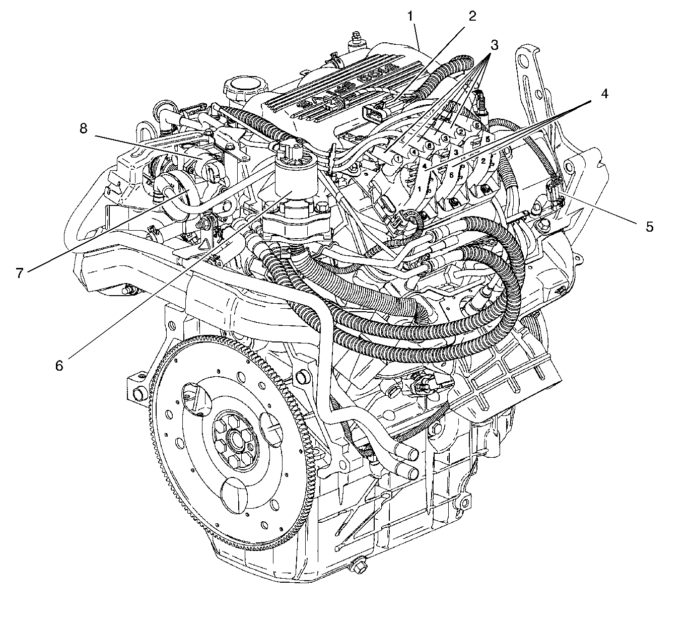
Figure 1:

Engine Composite View


Object Number: 215903  Size: LF
(1)Upper Intake Manifold
(2)Fuel Injector Connector
(3)Secondary Ignition Wires
(4)Ignition Coils
(5)Cam Shaft Position Sensor Connector
(6)EGR Valve
(7)Throttle Body Assembly
(8)IAC Valve
Figure 2:

Ignition System, TP Sensor, HO2S1, IAC and EGR Valve
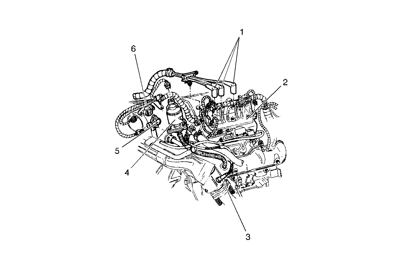

Object Number: 181125  Size: MF
(1)Ignition Wires
(2)Ignition Module
(3)Heated Oxygen Sensor 1 (HO2S1)
(4)Exhaust Gas Recirculation (EGR) Valve
(5)Throttle Position (TP) Sensor
(6)Idle Air Control (IAC) Valve
Figure 3:

IAT, MAF, A/C Pressure Sensors, Cruise Control Module
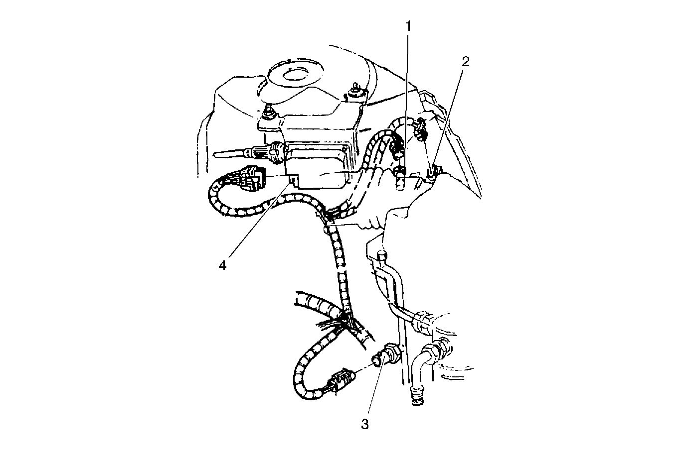

Object Number: 181091  Size: MF
(1)Intake Air Temperature (IAT) Sensor
(2)Mass Air Flow (MAF) Sensor
(3)A/C Referigerant Pressure Sensor
(4)Cruise Control Module
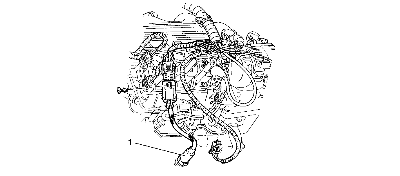
Figure 4:

Heated Oxygen Sensor 1 (HO2S1)


Object Number: 181275  Size: SF
(1)Heated Oxygen Sensor 1 (HO2S1)
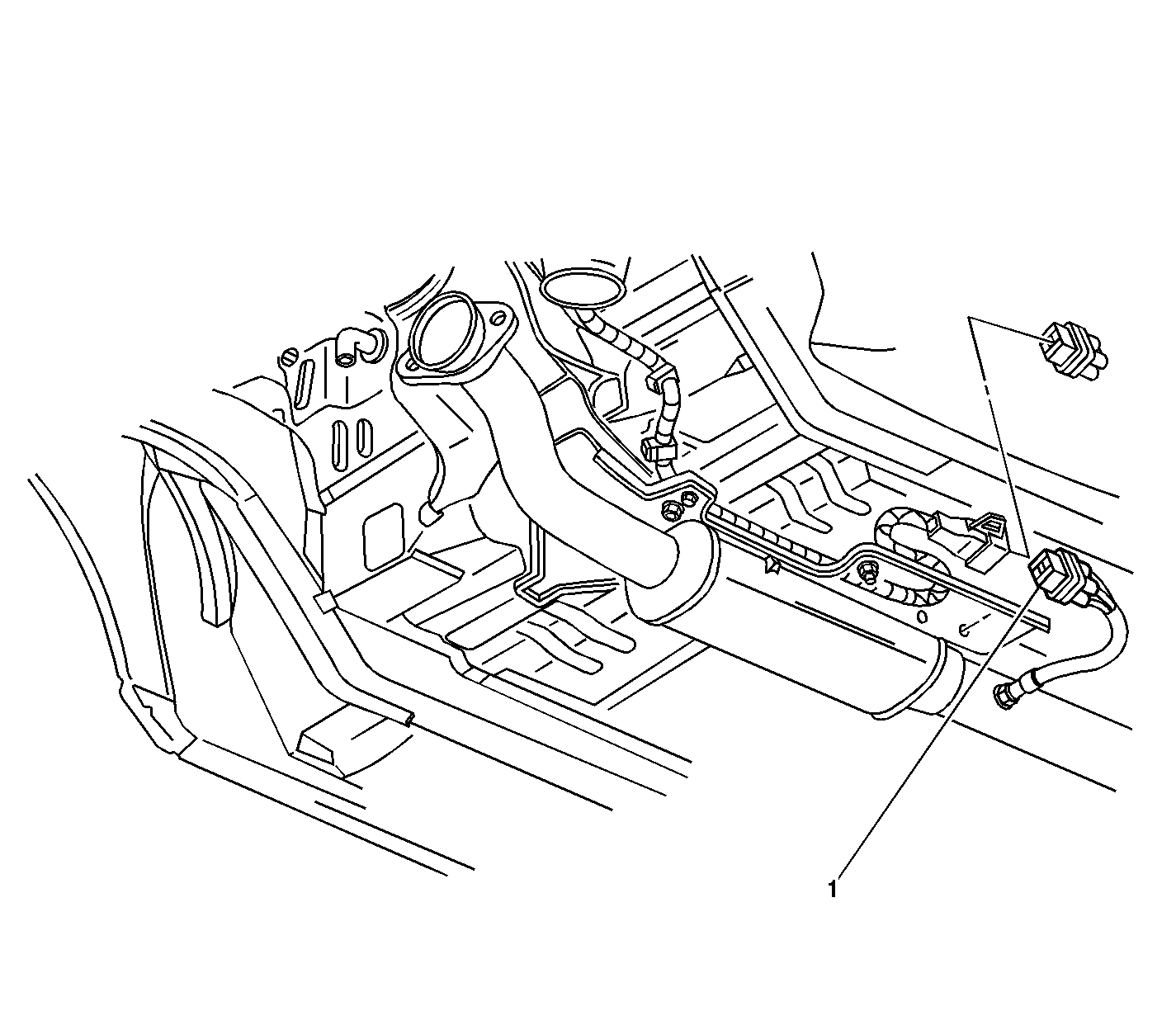
Figure 5:

Heated Oxygen Sensor 2 (HO2S2)


Object Number: 181135  Size: LF
(1)Heated Oxygen Sensor 2 (HO2S2)
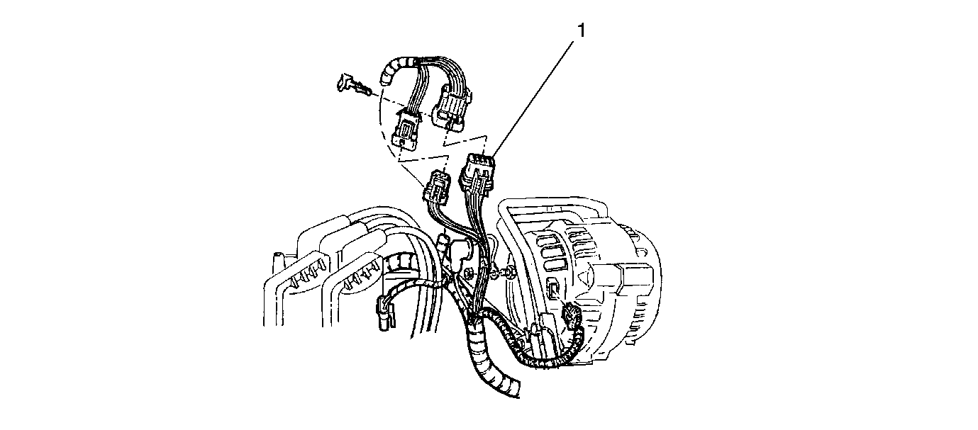
Figure 6:

Fuel Injector Harness 10-Way Connector


Object Number: 181305  Size: SF
(1)Fuel Injector Harness 10-Way Connector
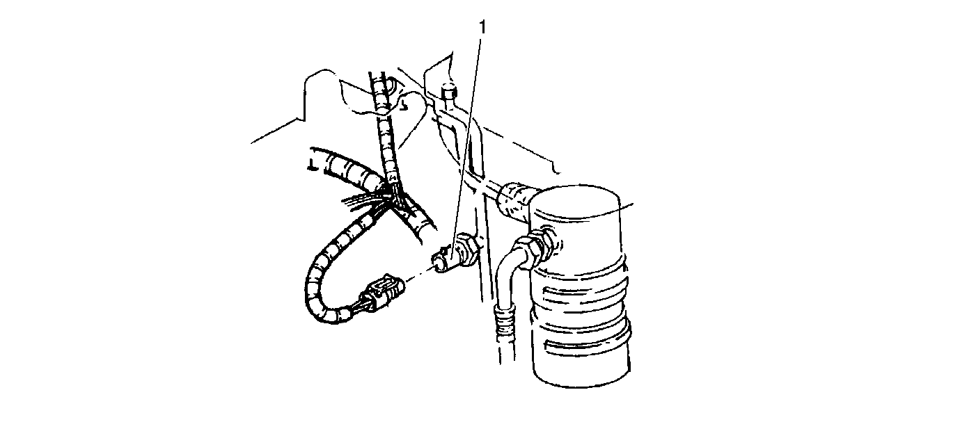
Figure 7:

A/C Refrigerant Pressure Sensor


Object Number: 181120  Size: SF
(1)A/C Referigerant Pressure Sensor
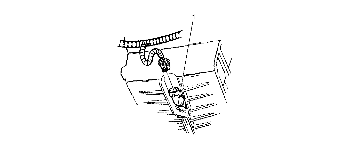
Figure 8:

Engine Oil Level Switch


Object Number: 181102  Size: SF
(1)Engine Oil Level Switch
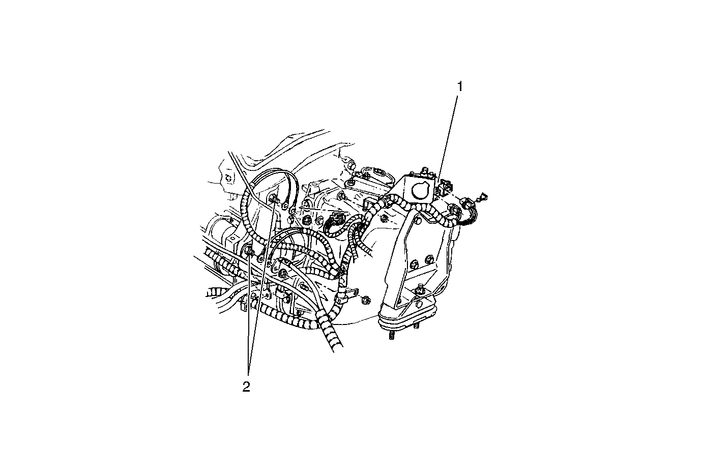
Figure 9:

Trans Range Switch, Engine Ground


Object Number: 181137  Size: MF
(1)Trans Range Switch
(2)Engine Grounds
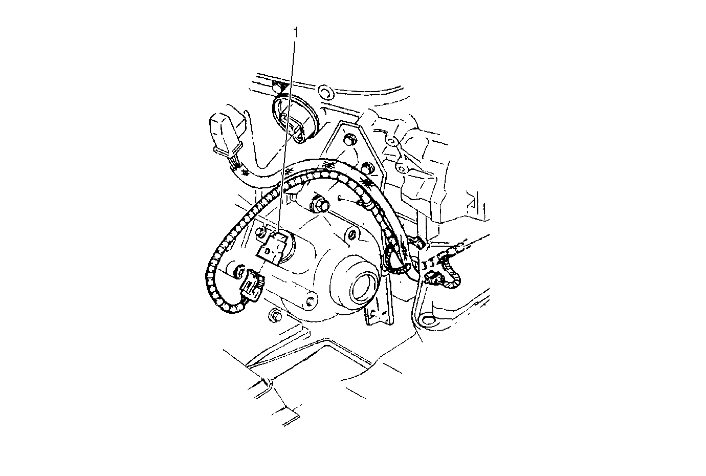
Figure 10:

Vehicle Speed Sensor (VSS)


Object Number: 181104  Size: MF
(1)Vehicle Speed Sensor (VSS)