Exhaust Manifold Replacement - Left Side L47
Removal Procedure
Caution: In order to avoid being burned, do not service the exhaust system while it is still hot. Service the system when it is cool.
Caution: Always wear protective goggles and gloves when removing exhaust parts as falling rust and sharp edges from worn exhaust components could result in serious personal injury.
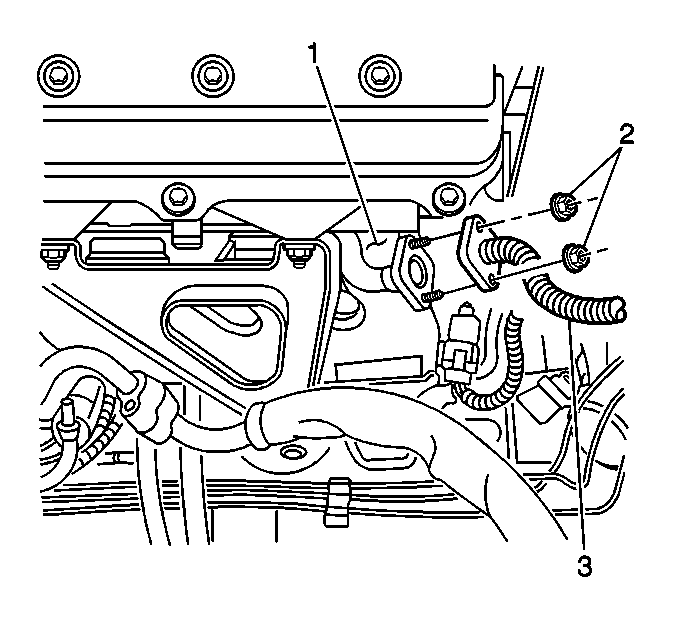
- Remove the two nuts (2) attaching the secondary AIR tube (3) to the exhaust manifold (1).
- Remove the secondary AIR tube (3) and the gasket from the exhaust manifold (1). Do not reuse the gasket.
- Remove the front engine mount bracket. Refer to Engine Front Mount Bracket Replacement in Engine Mechanical - 4.0 L.
- Raise and support the vehicle. Refer to Lifting and Jacking the Vehicle in General Information.
- Remove the oxygen sensor if replacement is necessary. Refer to Heated Oxygen Sensor Replacement - Bank 2 Sensor 1 in Engine Controls - 4.0 L.
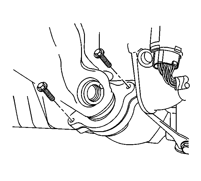
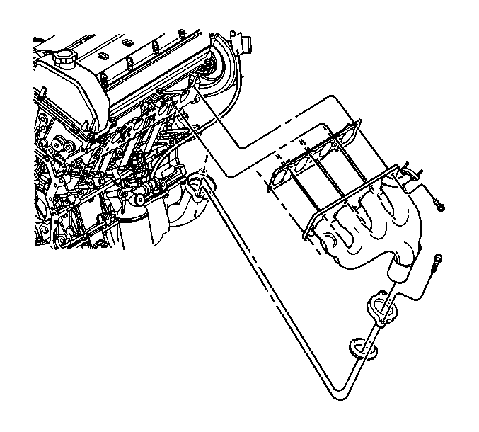
- Remove the two bolts attaching the left exhaust manifold to the front exhaust manifold pipe.
- Remove the left exhaust manifold retaining bolts.
- Remove the left exhaust manifold and the gasket from the engine. Do not reuse the gasket.
- Remove the front exhaust manifold pipe seal from the left exhaust manifold. Do not reuse the seal.
- Remove the exhaust manifold flange seal retainer.
- Clean and inspect the left exhaust manifold. Refer to Exhaust Manifold Cleaning and Inspection - Left Side in Engine Mechanical-4.0L Unit Repair.
Installation Procedure
- Place the retainer and a NEW front exhaust manifold pipe seal over the left exhaust manifold.
- Position a NEW exhaust manifold gasket between the left exhaust manifold and the left cylinder head.
- Insert the left exhaust manifold into the front exhaust manifold pipe and up to the left cylinder head.
- Install the left exhaust manifold bolts.
- Install the two bolts attaching the left exhaust manifold to the front exhaust manifold pipe.
- Install the oxygen sensor. Refer to Heated Oxygen Sensor Replacement - Bank 2 Sensor 1 in Engine Controls - 4.0 L.
- Install the front engine mount bracket. Refer to Engine Front Mount Bracket Replacement in Engine Mechanical -4.0 L.
- Lower the vehicle.
- Install the new gasket to the secondary AIR tube.
- Install the two nuts (2) attaching the secondary AIR tube (3) to the exhaust manifold (1).
Notice: Use the correct fastener in the correct location. Replacement fasteners must be the correct part number for that application. Fasteners requiring replacement or fasteners requiring the use of thread locking compound or sealant are identified in the service procedure. Do not use paints, lubricants, or corrosion inhibitors on fasteners or fastener joint surfaces unless specified. These coatings affect fastener torque and joint clamping force and may damage the fastener. Use the correct tightening sequence and specifications when installing fasteners in order to avoid damage to parts and systems.
Tighten
Tighten the exhaust manifold bolts to 25 N·m (18 lb ft).
Tighten
Tighten the front exhaust manifold pipe bolts to 25 N·m (18 lb ft).
Tighten
Tighten the secondary AIR tube nuts to 12 N·m (106 lb in).
