Tools Required
J 22610 Keystone Pliers.
Removal Procedure
- Raise and support the vehicle. Refer to Lifting and Jacking the Vehicle .
- Remove the wheel drive shaft from the vehicle. Refer to Wheel Drive Shaft Replacement .
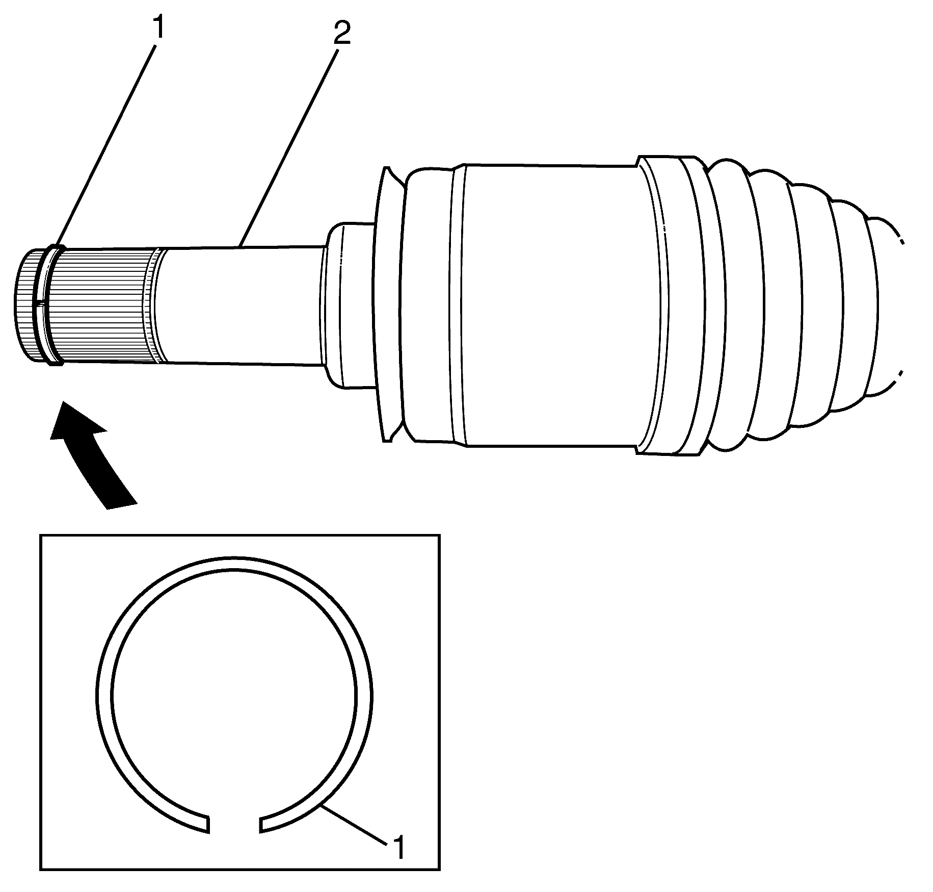
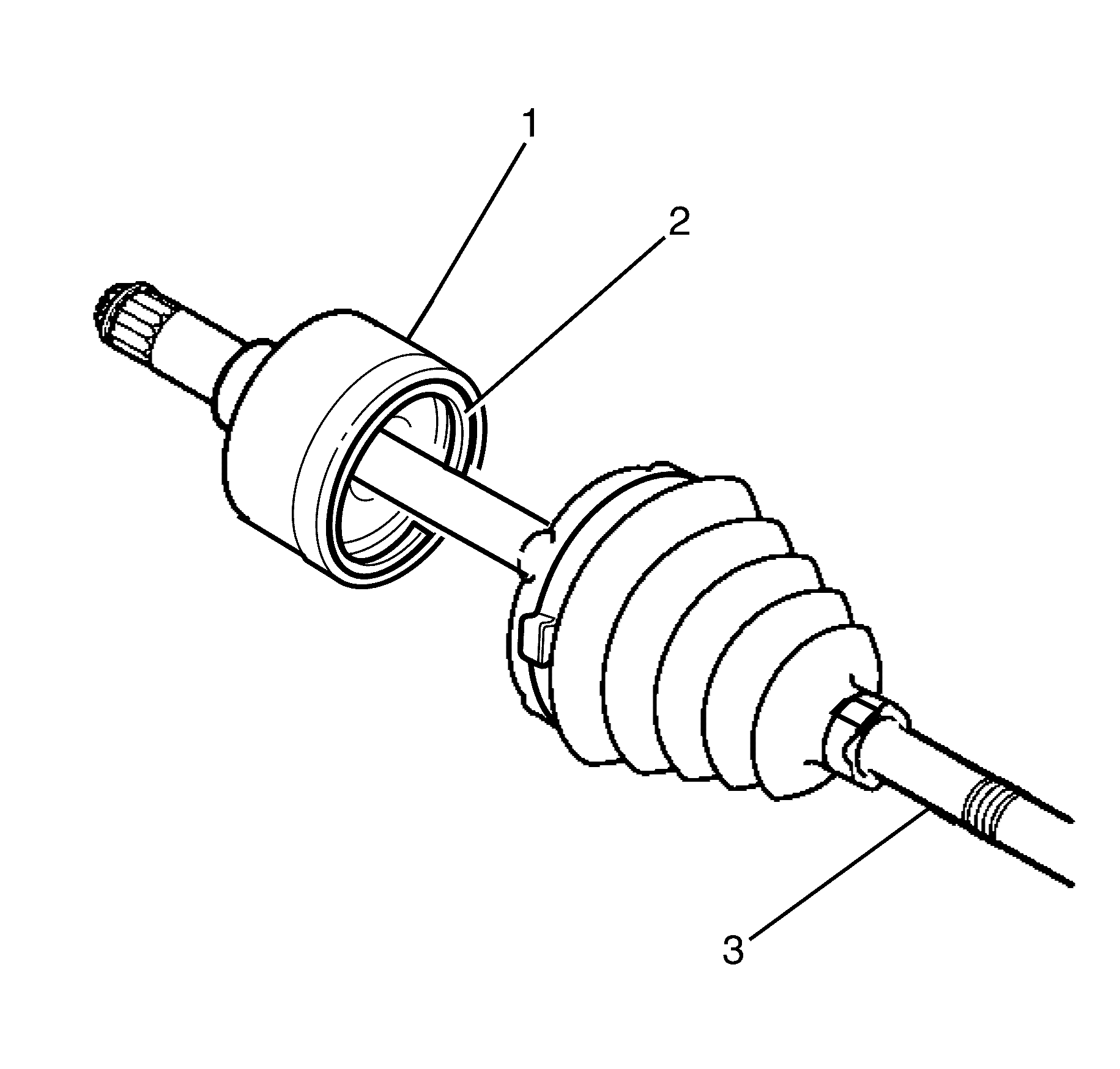
- Remove the inner joint boot small retaining clamp (1) and the large retaining clamp (2) from the inner joint boot (3).
- Move the inner joint boot (2) from the inner constant velocity joint (1) along the interconnecting shaft (3).
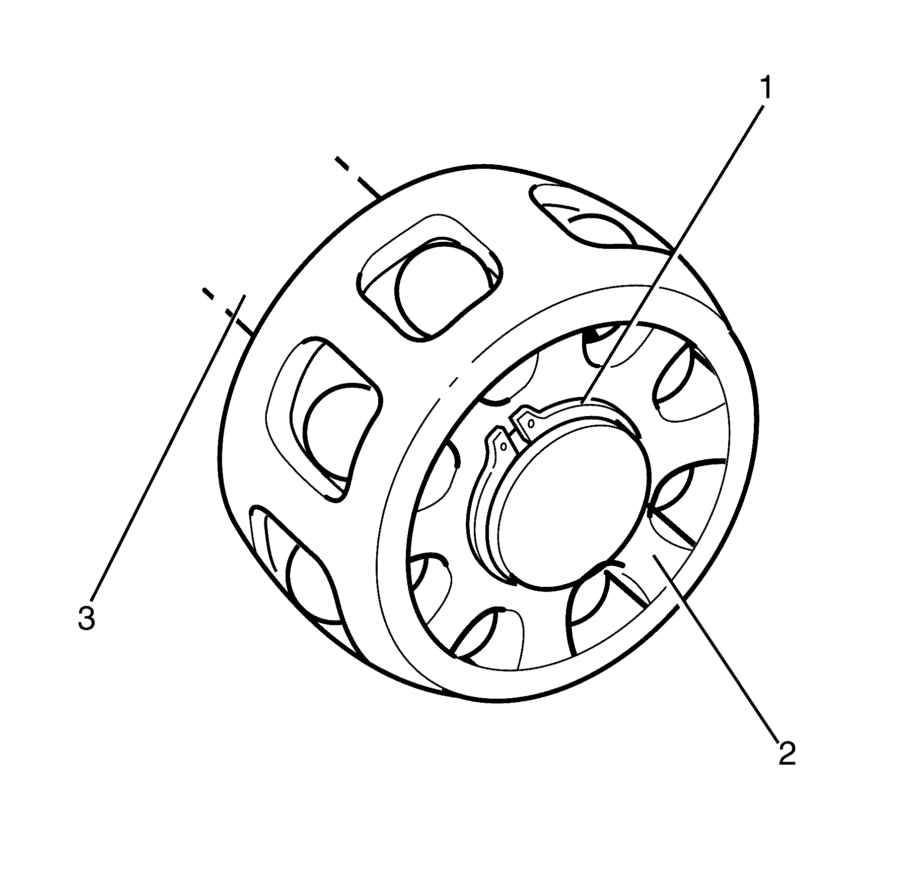
- Remove the circlip (2) from the outer race of the inner constant velocity joint (1).
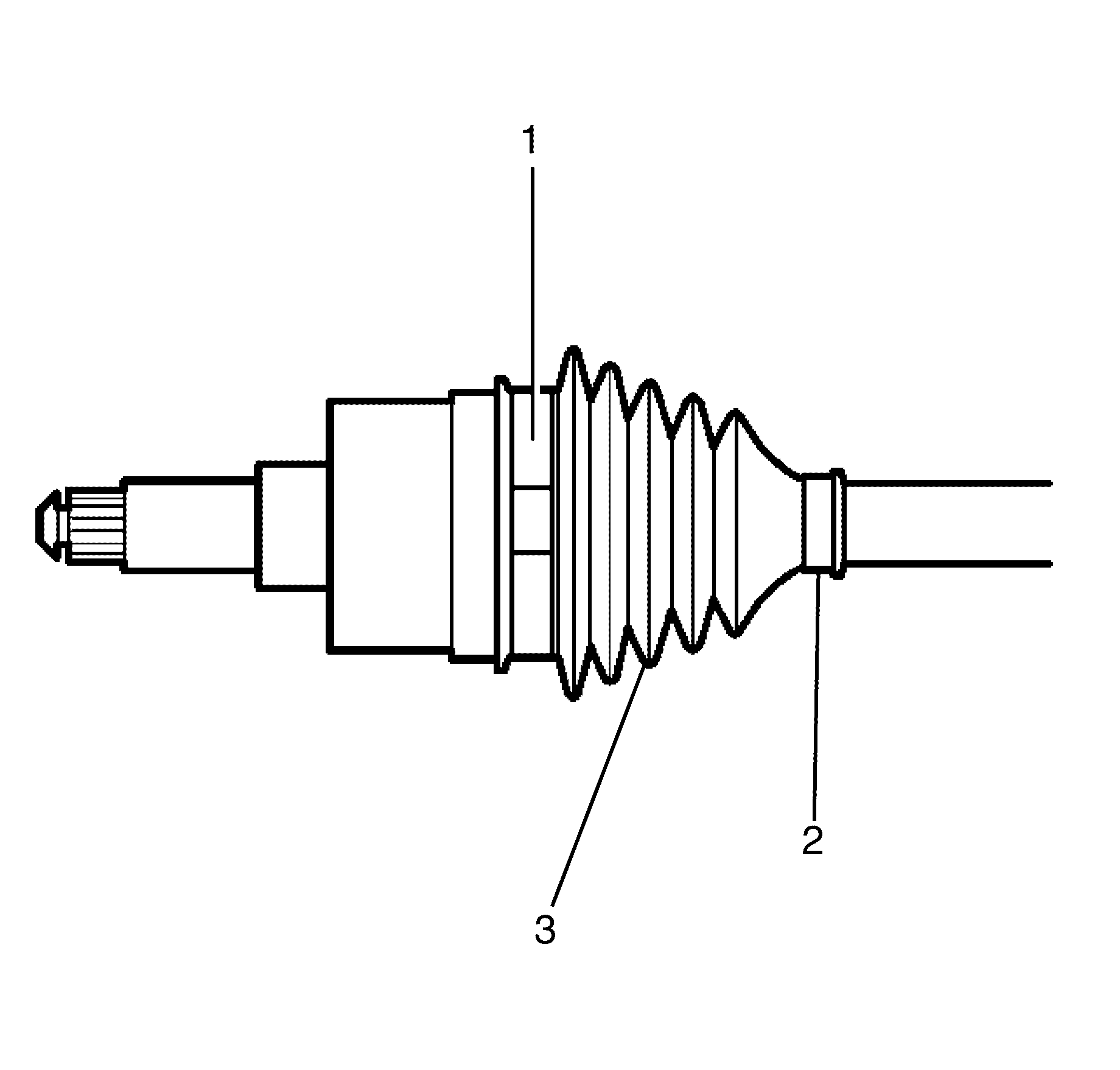
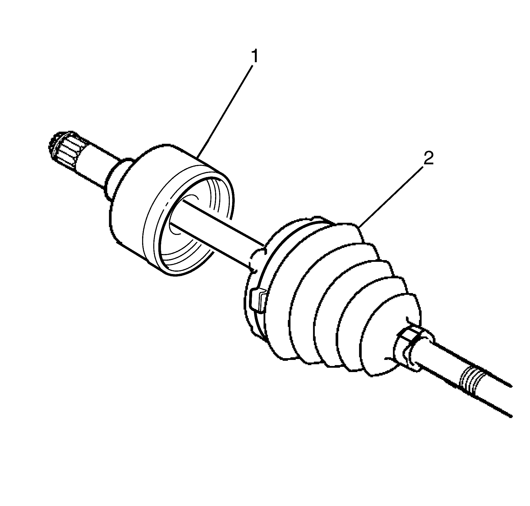
- Remove the inner constant velocity joint outer race (1) from the interconnecting shaft (3).
- Remove the circlip (1) from the inner constant velocity joint inner race (2).
- Remove the inner constant velocity joint inner race (2) from the interconnecting shaft (3).
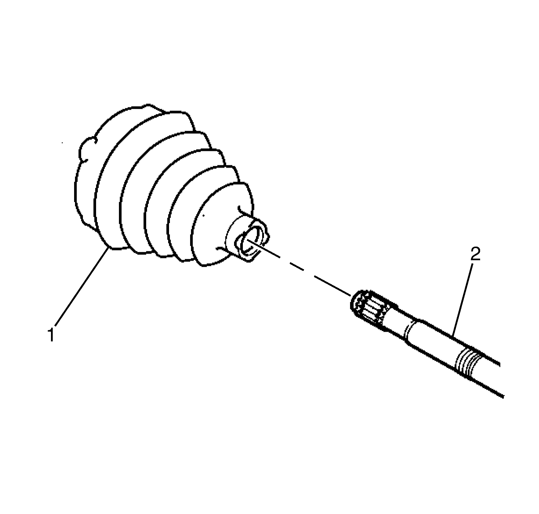
- Remove the inner joint boot (1) from the interconnecting shaft (2).
- Clean the grease from the interconnecting shaft (2).
Caution: Refer to Safety Glasses Caution in the Preface section.
Caution: Refer to Vehicle Lifting Caution in the Preface section.
Important: The inner joint boot small retaining clamp (2) and the inner joint boot large retaining clamp (1) are single use parts and must be discarded after use.
Discard the clamps.
Important: Take care as inner constant velocity balls can fall out when the inner constant velocity joint outer race (1) is removed.
Important: The circlip (1) is a single use part and must be discarded after use.
Discard the circlip.
Important: All traces of old grease and any contaminates must be removed.
Installation Procedure
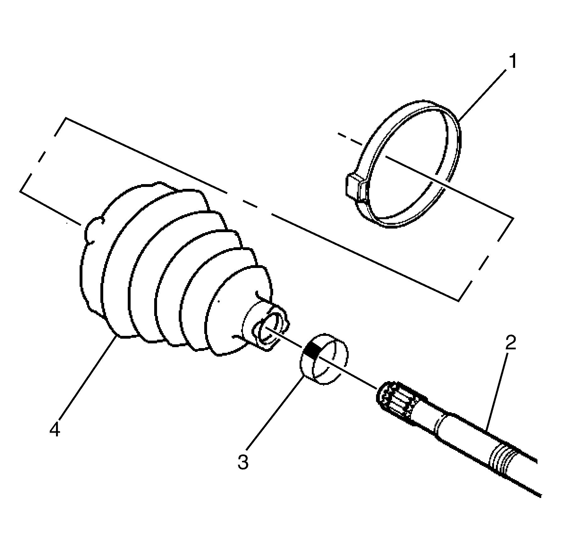
- Install the NEW inner joint boot large retaining clamp (1) and the NEW inner joint boot small retaining clamp (3) to the NEW inner joint boot (4).
- Install the NEW inner joint boot (4) along the interconnecting shaft (2).
- Install the inner race (2) to the interconnecting shaft (3).
- Install the NEW inner race snap ring (1) to the interconnecting shaft (3).
- Install the inner constant velocity joint outer race (1) to the interconnecting shaft (3).
- Install the NEW inner constant velocity joint outer race circlip (2) to the outer race of the inner constant velocity joint (1).
- Install the NEW inner joint boot (2) to the constant velocity joint (1).
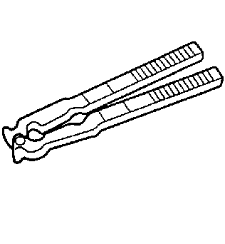
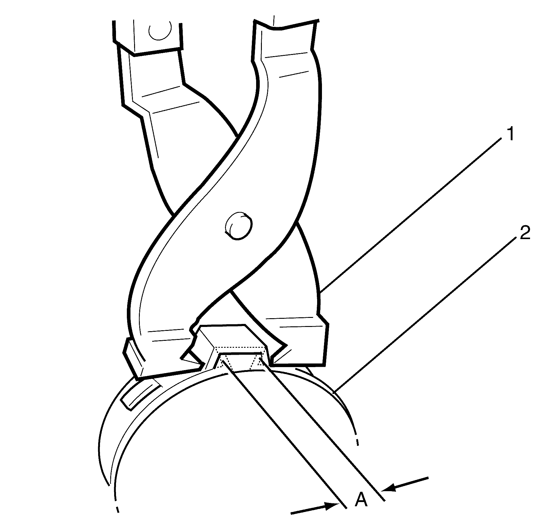
- Use J 22610 (1) to crimp retaining clamp (2). The crimped distance (A) must be between 1.2 - 4mm.
- Crimp the NEW inner joint boot large retaining clamp (1) and NEW inner joint boot small retaining clamp (2) to the NEW inner joint boot (3).
- The inner constant velocity joint dimension A is 280.3 mm (11.04 in) for V8 and 281.8 mm (11.09 in) for V6.
- Install the NEW snap ring (1) to the inner constant velocity joint (2).
- Fully cycle the inner constant velocity joint (2) several times to disperse grease throughout the inner constant velocity joint (2).
- Install the wheel drive shaft to the vehicle. Refer to Wheel Drive Shaft Replacement .
- Remove the safety stands.
- Lower the vehicle to the ground.
Important: The NEW inner joint boot large retaining clamp (1) and the NEW inner joint boot small retaining clamp (3) must not be fully tightened at this stage.
Do not fully tighten clamps.
Important: Pack grease around the inner constant velocity balls to aid in holding in place. Refer to Adhesives, Fluids, Lubricants, and Sealers .
Important: Install grease into the inner constant velocity joint (1) and the NEW inner joint boot (2). Refer to Adhesives, Fluids, Lubricants, and Sealers .
Notice: Refer to Fastener Notice in the Preface section.
Important: The NEW inner joint boot (1) must not be dimpled, stretched, or deformed. Always equalise the air pressure in the NEW inner boot with the joint in the centre of its plunge position and shape correctly by hand.