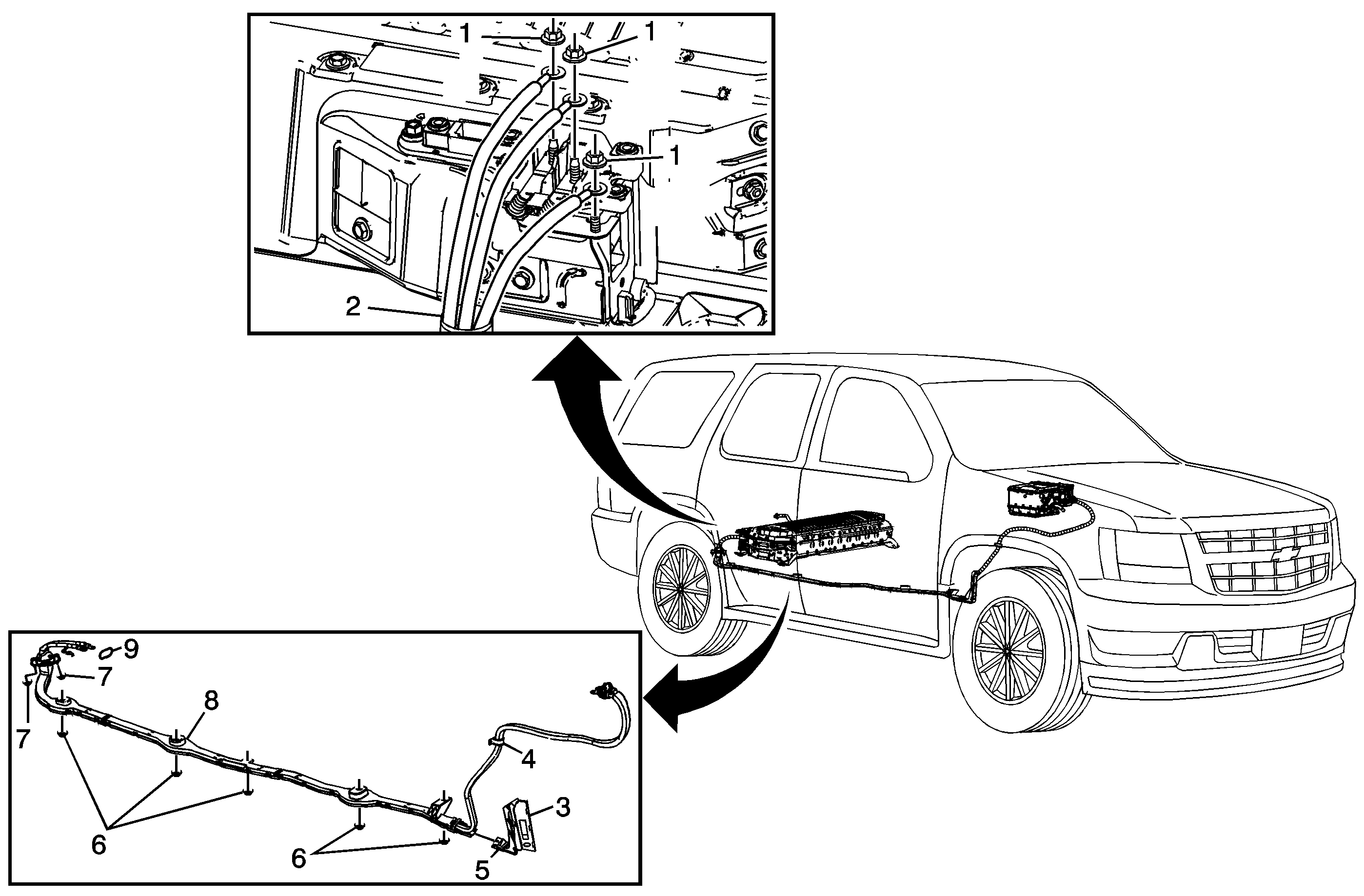
Callout
| Component Name
|
|
Danger: Always perform the High Voltage Disabling procedure prior to servicing any High
Voltage component or connection. Personal Protection Equipment (PPE) and proper procedures must be followed.
The High Voltage Disabling procedure will perform the following tasks:
| • | Identify how to disable high voltage. |
| • | Identify how to test for the presence of high voltage. |
| • | Identify condition under which high voltage is always present and personal protection equipment (PPE) and proper procedures must be followed. |
Preliminary Procedures
- Disable the high voltage at both the drive motor generator battery assembly and the drive motor generator control module assembly. Refer to
High Voltage Disabling.
- Remove the right front fender bracket. Refer to
Front Fender Rear Upper Bracket Replacement.
- Remove the control module sight shield. Refer to
Drive Motor Generator Control Module Sight Shield Replacement.
- Remove the right front wheelhouse liner. Refer to
Front Wheelhouse Liner Replacement - Left Side.
- Remove the electric power steering control module. Refer to
Electronic Power Steering Motor Control Module Replacement.
- Remove the rear muffler insulator and 2 catalytic converter bolts. Refer to
Exhaust Muffler Replacement.
- Remove both resonator insulators. Refer to
Resonator Replacement.
|
1
| Drive Motor Battery 300 Volt Negative Cable Terminal Fastener (Qty: 3)
Caution: Refer to Fastener Caution in the Preface section.
Tighten
9 N·m (80 lb in) |
2
| Drive Motor Battery 300 Volt Positive and Negative Cable
ProcedureRemove terminals from studs.
|
3
| 300 Volt Positive and Negative Cable Front Elbow Hinge Panel (Qty: 3)
Tip
Remove and replace plastic tie straps. Open all panels on cable front elbow. |
4
| 300V Positive and Negative Cable Retainer
|
5
| 300V Positive and Negative Cable Front Elbow
|
6
| 300V Positive and Negative Cable Nut (Qty: 5)
Tighten
10 N·m (89 lb in) |
7
| Drive Motor Battery 300 Volt Cable Floor Grommet Nut (Qty: 2)
Tighten
9 N·m (80 lb in) |
8
| Drive Motor Battery 300 Volt Positive and Negative Cable
Procedure
- Push the drive motor battery 300 volt positive and negative cable through the floor grommet.
- Raise and support the vehicle. Refer to
Lifting and Jacking the Vehicle.
- Pull cable rearward to remove cable from floor.
- Push cable forward of the rear cross member.
- Pull the cable out from under the rear cross member.
|
9
| Cable Gasket
ProcedureAfter the cable has been replaced and the re-assembly of the drive motor generator battery, enable the HV system. Refer to
High Voltage Enabling.
Tip
New gasket must be used. |

