Exhaust Muffler Replacement With LMG, LY2 or LY5
Tools Required
J 38185 Hose Clamp Pliers
Removal Procedure
- Raise and support the vehicle. Refer to Lifting and Jacking the Vehicle.
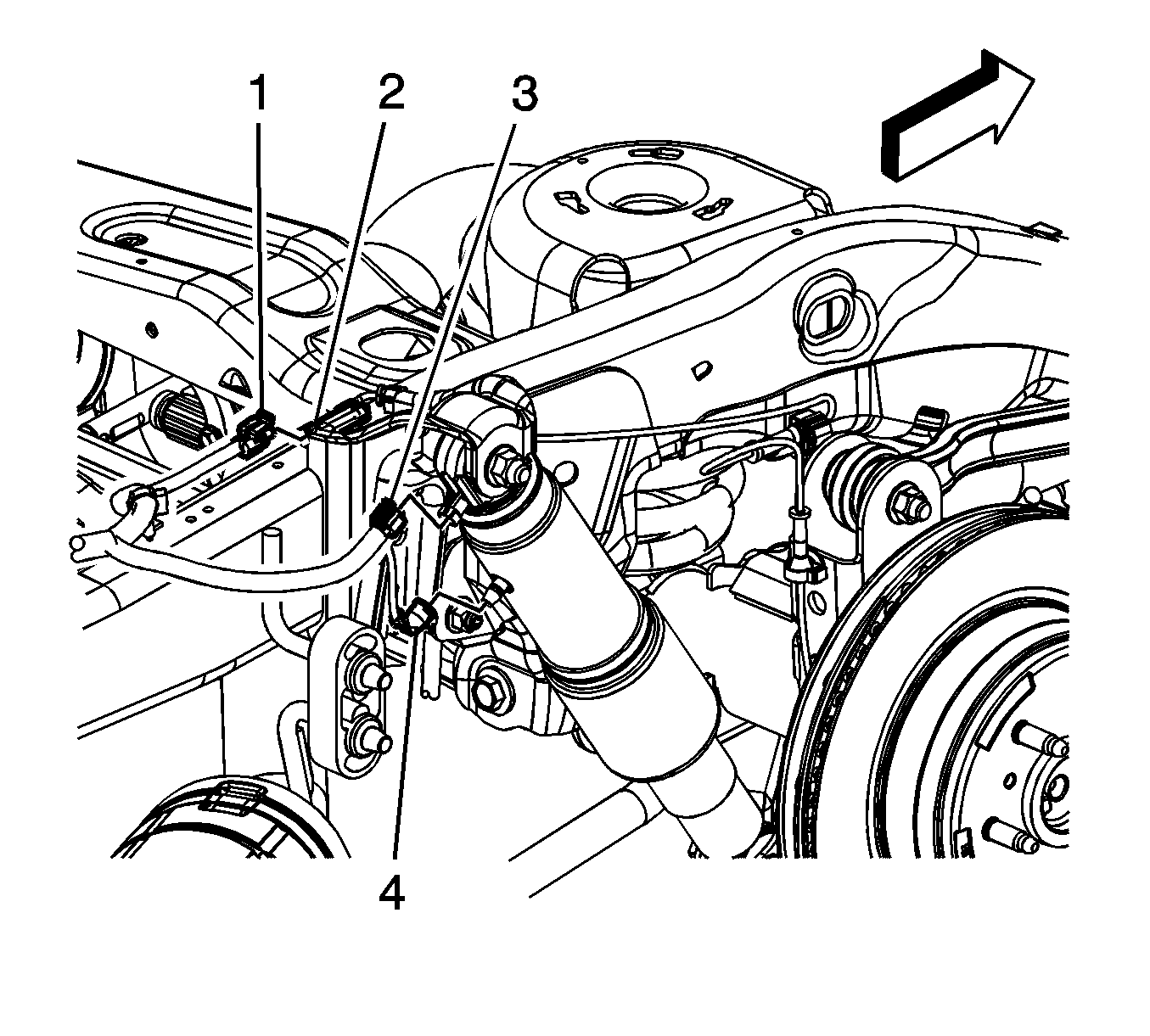
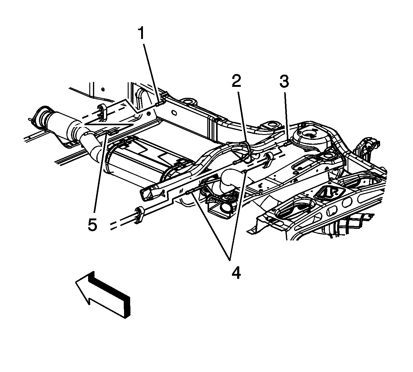
- Disconnect the chassis wiring harness electrical connector (1) from the right rear wheel speed sensor wiring harness electrical connector (2).
- If the vehicle is equipped with regular production option (RPO) Z55, disconnect the chassis wiring harness electrical connector (3) from the right rear shock absorber.
- If the vehicle is equipped with RPO Z55, disconnect the right rear air line from the shock absorber.
- Remove the right rear wheel speed sensor wiring harness electrical connector clip from the frame.
- Remove the right rear wheel speed sensor wiring harness clips from the frame and the control arm bracket.
- Disconnect the right rear automatic level control sensor link rod from the sensor. Perform the following:
- Install a suitable adjustable jack under the rear axle.
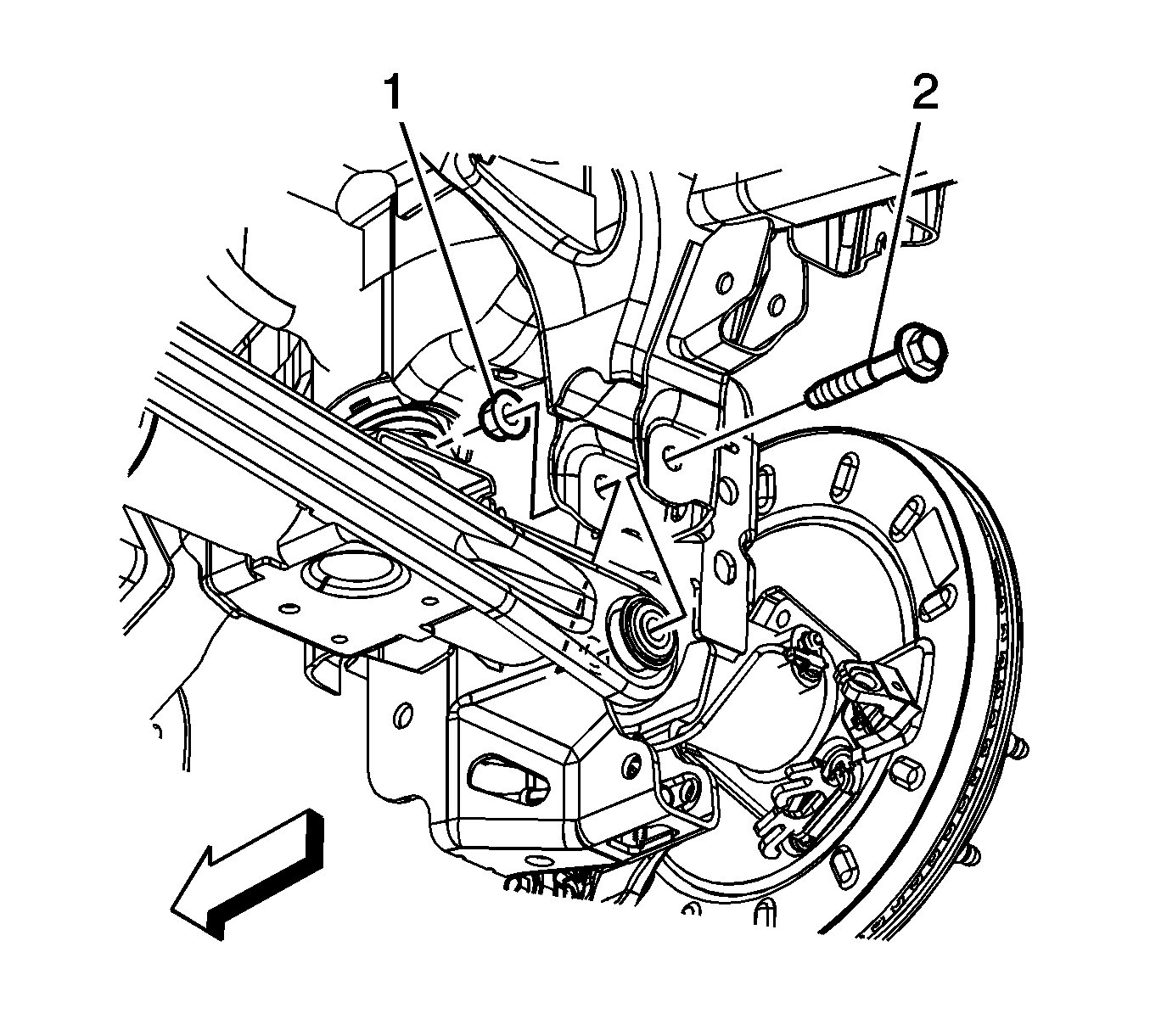
- Remove the right axle tie rod bolt (2) and nut (1).
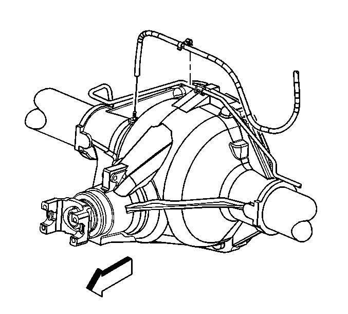
- Remove the rear axle vent hose from the rear axle, if necessary.
- Remove the vent hose swivel clip from the rear brake crossover pipe, if necessary.
- Remove the right rear stabilizer shaft link to frame bolt and nut.
- Remove the right rear stabilizer shaft link from the frame.
- Remove the right rear shock absorber lower bolt and nut.
- Lower the right side of the rear axle using the adjustable jack in order to remove the muffler.
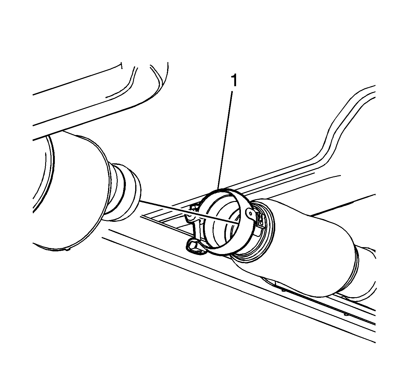
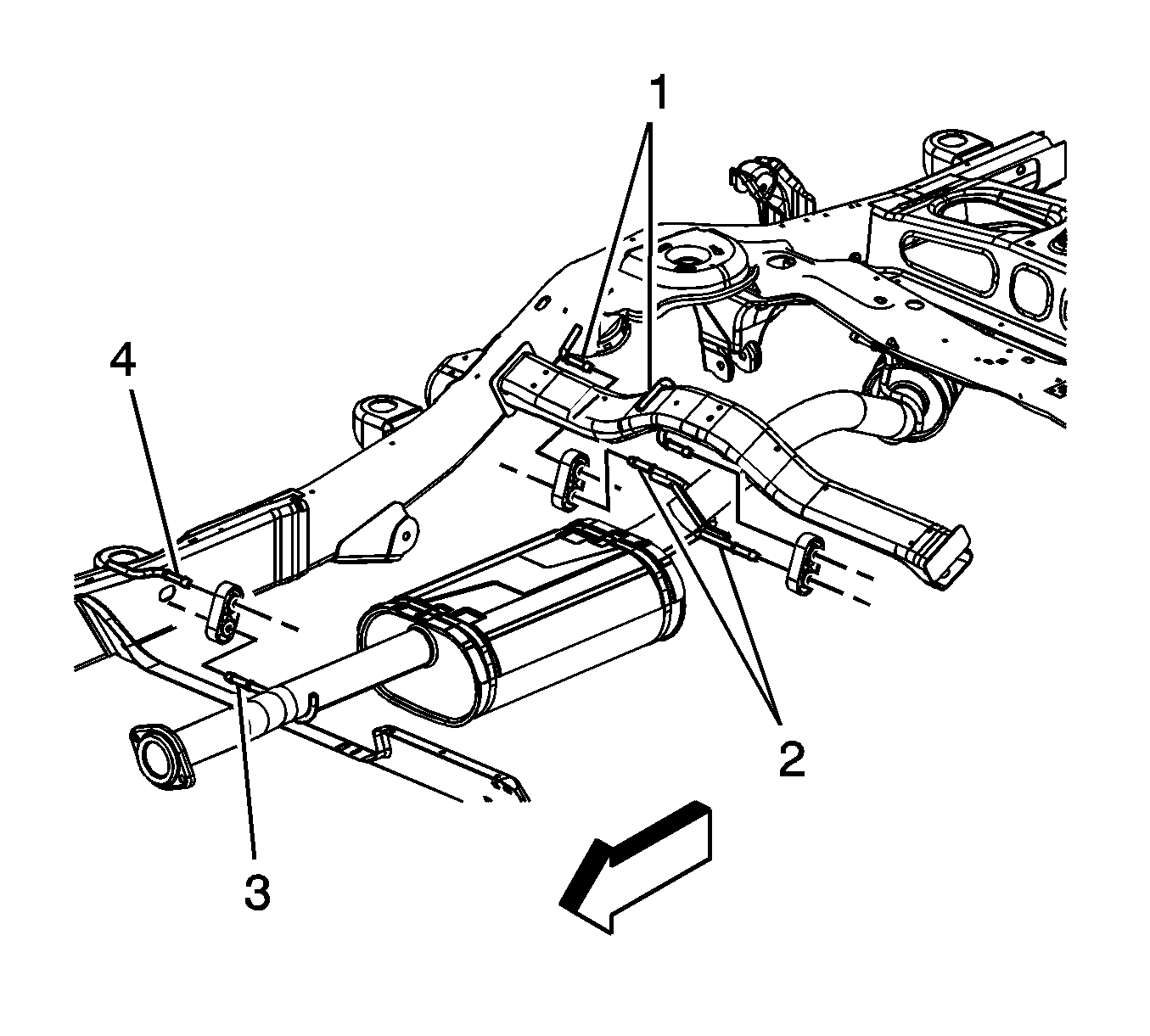
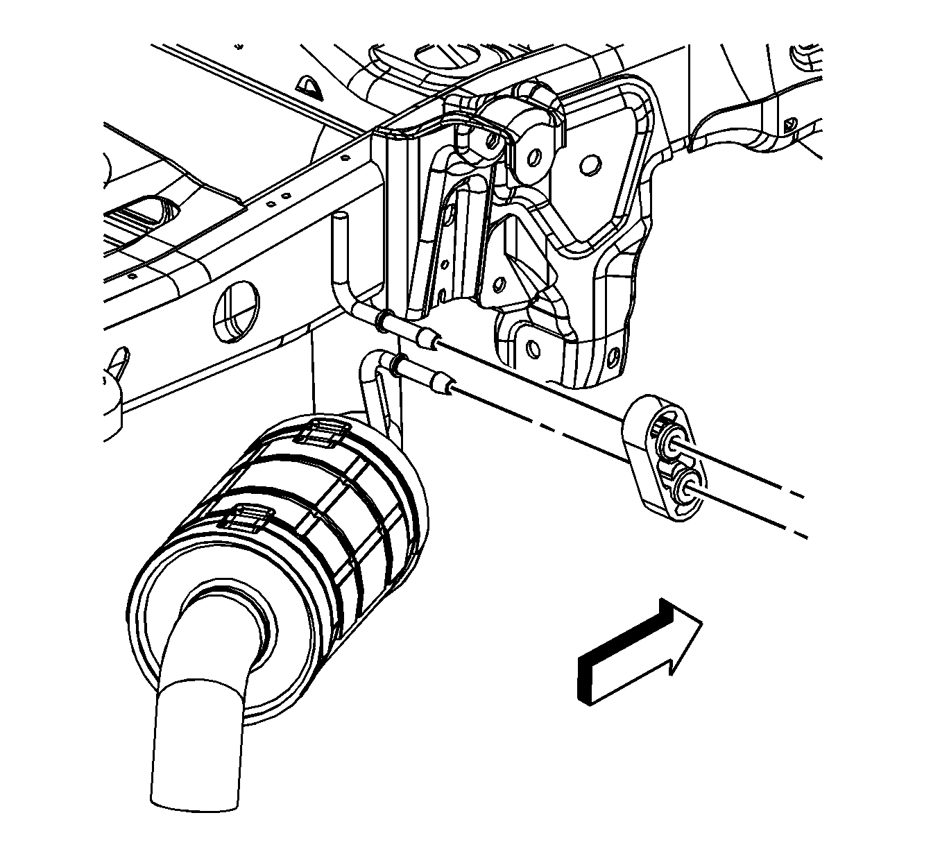
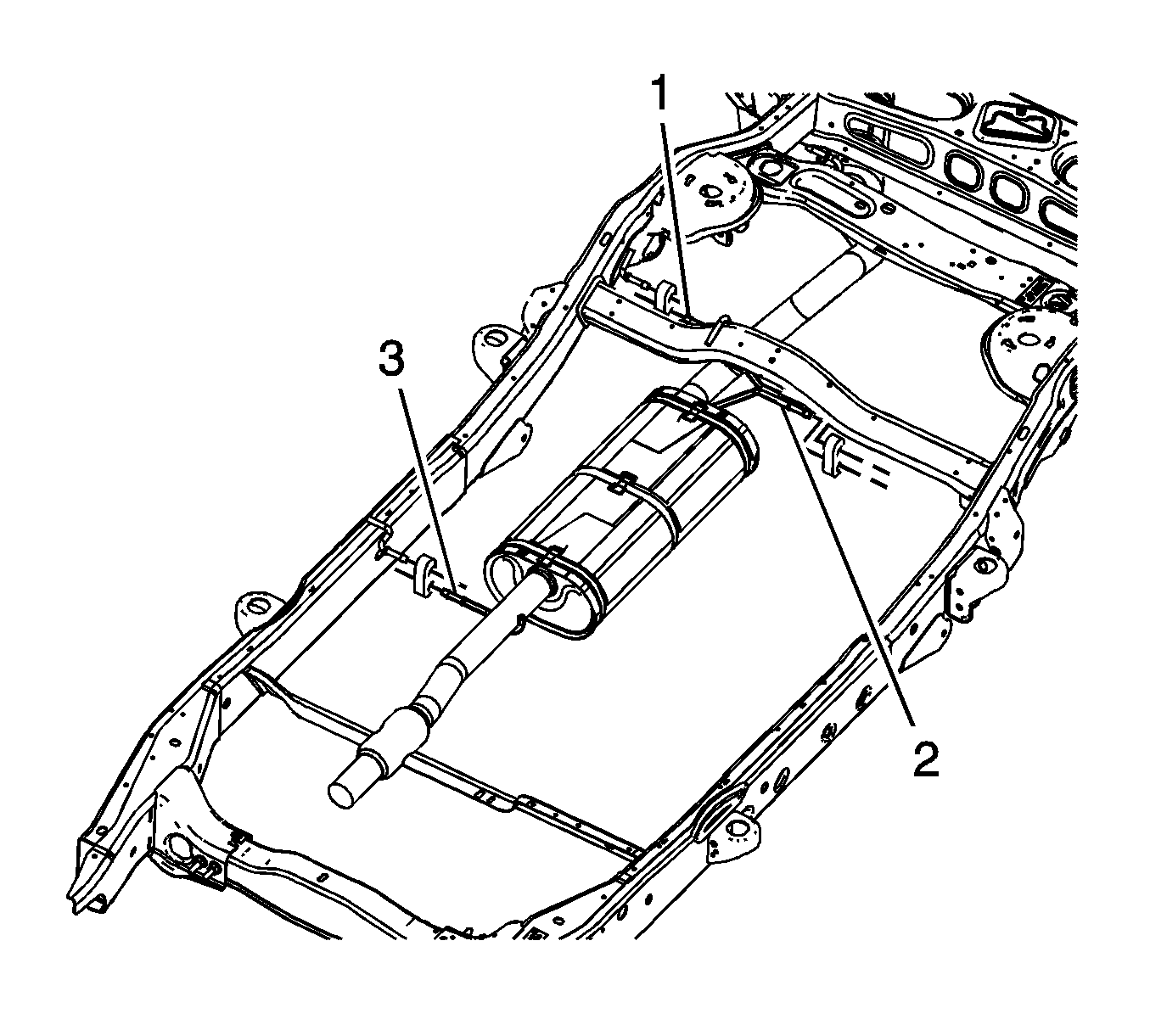
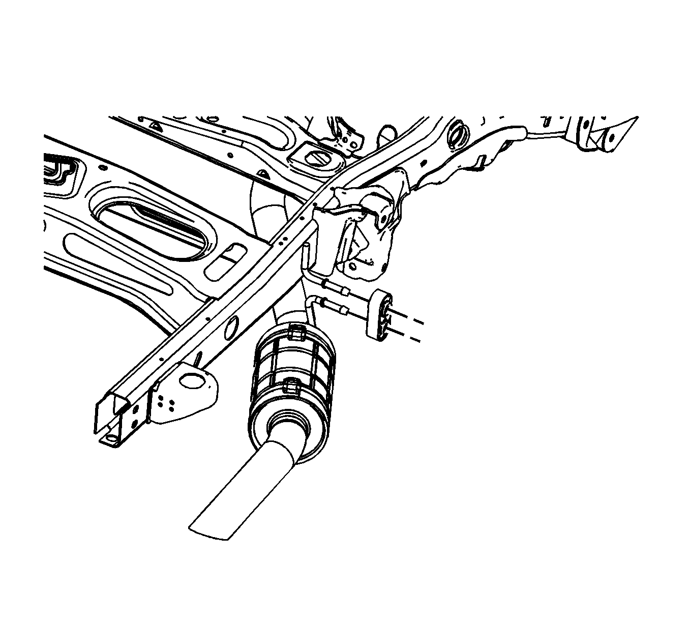
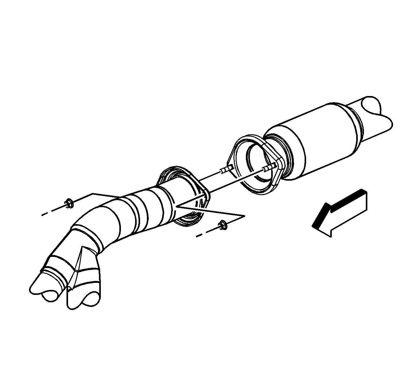
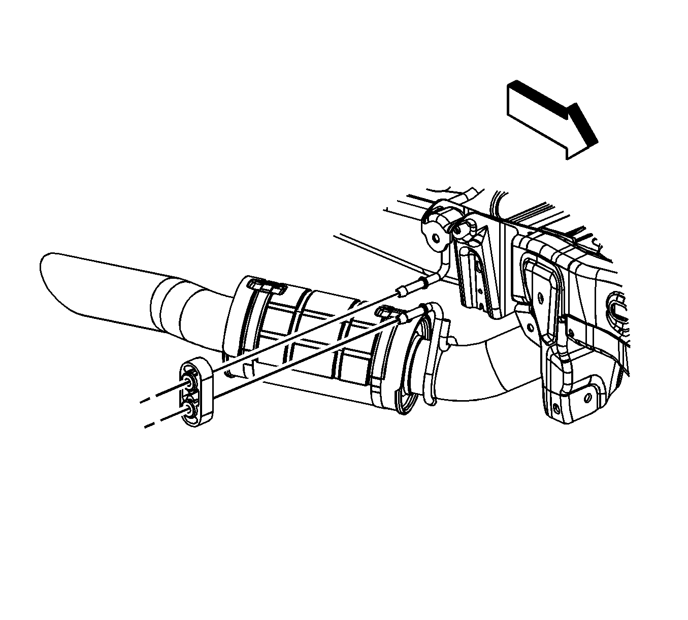
- Loosen the catalytic converter to muffler camp bolt.
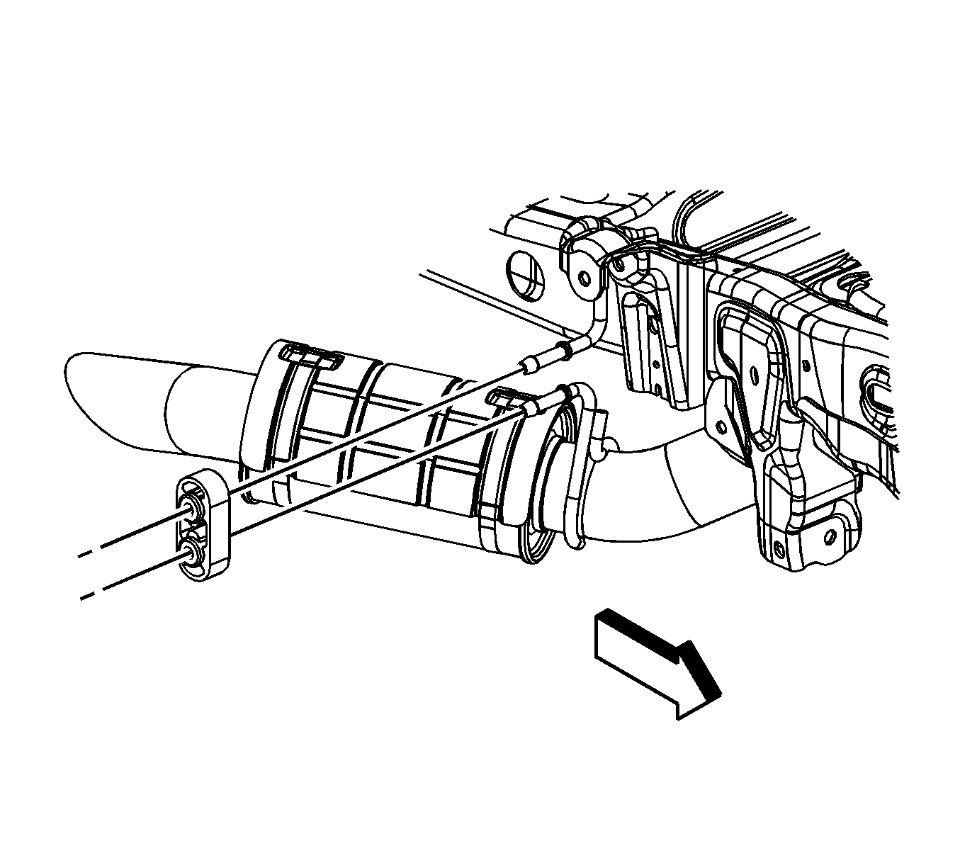
- Lubricate the insulators where the muffler assembly hangers are inserted in order to ease in removal.
- With the aid of an assistant, remove the insulators from the exhaust system hangers (2 and 3).
- With the aid of an assistant, remove the insulator from the exhaust system hanger near the resonator.
- Remove the muffler assembly.
Important: The rear axle wiring harness clip is a one way clip with a D-shape section. The clip can only be installed and/or removed in only one direction.
Important: Do not attempt to pry the rear suspension sensor link rod from the rear position sensor ball stud.
| 7.1. | Support the sensor lever with your hand. |
| 7.2. | Twist the link rod ball in order to separate it from the ball stud. |
Important: During removal, do not over extend the flex coupler as internal damage may occur.
Installation Procedure
- Lubricate the insulators where the muffler assembly hangers are inserted for ease of installation.
- With the aid of an assistant, install the muffler assembly.
- With the aid of an assistant, install the insulators to the exhaust system hangers (2 and 3).
- Install the insulator to the exhaust system hanger near the resonator.
- Position the muffler assembly to the three-way catalytic converter and tighten the clamp bolt to 44 N·m (32 lb ft).
- Raise the right side of the rear axle into position using the adjustable jack.
- Install the right rear shock absorber lower bolt and nut and tighten to 95 N·m (70 lb ft).
- Install the right rear stabilizer shaft link to the frame.
- Install the right rear stabilizer shaft link to frame bolt and nut and tighten to 65 N·m (48 lb ft).
- Install the right rear axle tie rod bolt (2) and nut (1) and tighten to 105 N·m (77 lb ft).
- Install the rear axle vent hose to the rear axle, if necessary.
- Install the vent hose swivel clip to the rear brake crossover pipe, if necessary.
- Using the J 38185 install the right rear link rod to the ball studs on the sensors.
- Install the right rear wheel speed sensor wiring harness clips to the frame and the control arm bracket.
- Install the right rear wheel speed sensor wiring harness electrical connector clip to the frame.
- If the vehicle is equipped with RPO Z55, connect the right rear air line to the shock absorber.
- If the vehicle is equipped with RPO Z55, connect the chassis wiring harness electrical connector (3) to the right rear shock absorber.
- Connect the chassis wiring harness electrical connector (1) to the right rear wheel speed sensor wiring harness electrical connector (2).
- Lower the vehicle.
Notice: To prevent internal damage to the flexible coupling of the catalytic converter assembly, the converter must be supported. The vertical movement at the rear of the catalytic converter assembly must not exceed 6 degrees up or down.
Caution: Refer to Fastener Caution in the Preface section.
Important: The rear axle wiring harness clip is a one way clip with a D-shape section. The clip can only be installed and/or removed in only one direction.
Exhaust Muffler Replacement With LC9, LMG, LY5 or L76
Tools Required
J 38185 Hose Clamp Pliers
Removal Procedure
Warning: Refer to Exhaust Service Warning in the Preface section.
- Raise and support the vehicle. Refer to Lifting and Jacking the Vehicle.
- Disconnect the chassis wiring harness electrical connector (1) from the right rear wheel speed sensor wiring harness electrical connector (2).
- If the vehicle is equipped with regular production option (RPO) Z55, disconnect the chassis wiring harness electrical connector (3) from the right rear shock absorber.
- If the vehicle is equipped with RPO Z55, disconnect the right rear air line from the shock absorber.
- Remove the right rear wheel speed sensor wiring harness electrical connector clip from the frame.
- Remove the right rear wheel speed sensor wiring harness clips from the frame and the control arm bracket.
- Disconnect the right rear automatic level control sensor link rod from the sensor. Perform the following:
- Install a suitable adjustable jack under the rear axle.
- Remove the right axle tie rod bolt (2) and nut (1).
- Remove the rear axle vent hose from the rear axle, if necessary.
- Remove the vent hose swivel clip from the rear brake crossover pipe, if necessary.
- Remove the right rear stabilizer shaft link to frame bolt and nut.
- Remove the right rear stabilizer shaft link from the frame.
- Remove the right rear shock absorber lower bolt (4) and nut (3).
- Lower the right side of the rear axle using the adjustable jack in order to remove the muffler.
- Loosen the catalytic converter to muffler clamp bolt (1).
- Lubricate the insulators where the muffler assembly hangers are inserted in order to ease in removal.
- With the aid of an assistant, remove the insulators from the exhaust system hangers (1, 2, and 3).
- With the aid of an assistant, remove the insulator from the exhaust system hanger near the resonator.
- Remove the muffler assembly.
Important: The rear axle wiring harness clip is a one way clip with a D-shape section. The clip can only be installed and/or removed in only one direction.
Important: Do not attempt to pry the rear suspension sensor link rod from the rear position sensor ball stud.
| 7.1. | Support the sensor lever with your hand. |
| 7.2. | Twist the link rod ball in order to separate it from the ball stud. |
Important: During removal, do not over extend the flex coupler as internal damage may occur.
Installation Procedure
- Lubricate the insulators where the muffler assembly hangers are inserted for ease of installation.
- With the aid of an assistant, install the muffler assembly.
- With the aid of an assistant, install the insulators to the exhaust system hangers (1, 2, and 3).
- Install the insulator to the exhaust system hanger near the resonator.
- Position the muffler assembly to the three-way catalytic converter and tighten the clamp bolt to 44 N·m (32 lb ft)
- Raise the rear axle into position using the adjustable jack.
- Install the right rear shock absorber lower bolt and nut and tighten to 95 N·m (70 lb ft).
- Install the right rear stabilizer shaft link to the frame.
- Install the right rear stabilizer shaft link to frame bolt and nut and tighten to 65 N·m (48 lb ft).
- Install the right rear axle tie rod bolt (2) and nut (1).
- Install the rear axle vent hose to the rear axle, if necessary.
- Install the vent hose swivel clip to the rear brake crossover pipe, if necessary.
- Using the J 38185 install the right rear link rod to the ball studs on the sensors.
- Install the right rear wheel speed sensor wiring harness clips to the frame and the control arm bracket.
- Install the right rear wheel speed sensor wiring harness electrical connector clip to the frame.
- If the vehicle is equipped with RPO Z55, connect the right rear air line to the shock absorber.
- If the vehicle is equipped with RPO Z55, connect the chassis wiring harness electrical connector (3) to the right rear shock absorber.
- Connect the chassis wiring harness electrical connector (1) to the right rear wheel speed sensor wiring harness electrical connector (2).
- Lower the vehicle.
Important: During installation, do not over extend the flex coupler as internal damage may occur.
Caution: Refer to Fastener Caution in the Preface section.
Important: The rear axle wiring harness clip is a one way clip with a D-shape section. The clip can only be installed and/or removed in only one direction.
Exhaust Muffler Replacement With LFA
Removal Procedure
Warning: Refer to Exhaust Service Warning in the Preface section.
- Raise and support the vehicle. Refer to Lifting and Jacking the Vehicle.
- Loosen the catalytic converter to muffler clamp bolt (1).
- Disconnect the muffler assembly from the resonator. Refer to Resonator Replacement
- Lubricate the insulators where the muffler pipe hangers are inserted in order to ease in removal.
- Remove the insulators from the exhaust system hangers (1, 2, and 3).
- With the aid of an assistant, remove the muffler pipe assembly from the vehicle.
Installation Procedure
- Lubricate the insulators (1) where the muffler pipe hangers are inserted for ease of installation.
- With the aid of an assistant, install the muffler pipe assembly to the exhaust system hangers (1, 2, and 3).
- Connect the muffler assembly to the resonator. Refer to Resonator Replacement
- Position the muffler assembly to the three-way catalytic converter clamp bolt (1) and tighten to 44 N·m (32 lb ft).
- Lower the vehicle.
- Inspect the exhaust system for leaks.
Important: During installation, do not over extend the flex coupler as internal damage may occur.
Caution: Refer to Fastener Caution in the Preface section.
Exhaust Muffler Replacement With L92
Tools Required
J 38185 Hose Clamp Pliers
Removal Procedure
Warning: Refer to Exhaust Service Warning in the Preface section.
- Remove the right rear wheel and tire. Refer to Tire and Wheel Removal and Installation.
- Disconnect the chassis wiring harness electrical connector (1) from the right rear wheel speed sensor wiring harness electrical connector (2).
- If the vehicle is equipped with regular production option (RPO) Z55, disconnect the chassis wiring harness electrical connector (3) from the right rear shock absorber.
- If the vehicle is equipped with RPO Z55, disconnect the right rear air line from the shock absorber.
- Remove the right rear wheel speed sensor wiring harness electrical connector clip from the frame.
- Remove the right rear wheel speed sensor wiring harness clips from the frame and the control arm bracket.
- Disconnect the right rear automatic level control sensor link rod from the sensor. Perform the following:
- Install a suitable adjustable jack under the rear axle.
- Remove the right axle tie rod bolt (2) and nut (1).
- Remove the rear axle vent hose from the rear axle, if necessary.
- Remove the vent hose swivel clip from the rear brake crossover pipe, if necessary.
- Remove the right rear stabilizer shaft link to frame bolt and nut.
- Remove the right rear stabilizer shaft link from the frame.
- Remove the right rear shock absorber lower bolt (4) and nut (3).
- Lower the right side of the rear axle using the adjustable jack in order to remove the muffler.
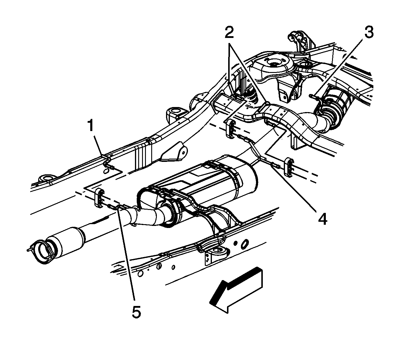
- Remove the muffler to catalytic converter nuts.
- Separate the hanger.
- If the vehicle is a Yukon Denali or Escalade perform the following steps, otherwise proceed to step 26.
- Lubricate the insulators where the muffler assembly hangers are inserted in order to ease in removal.
- With the aid of an assistant, remove the insulators from the exhaust system hangers (4, and 5).
- With the aid of an assistant, remove the insulator from the exhaust system hanger near the resonator.
- Remove the muffler assembly.
- If the vehicle is a Yukon XL, Yukon Denali XL, Escalade ESV, or Escalade EXT perform the following steps.
- Lubricate the insulators where the muffler assembly hangers are inserted in order to ease in removal.
- With the aid of an assistant, remove the insulators from the exhaust system hangers (3, 4, and 5).
- With the aid of an assistant, remove the insulator from the exhaust system hanger near the resonator.
- Remove the muffler assembly.
Important: The rear axle wiring harness clip is a one way clip with a D-shape section. The clip can only be installed and/or removed in only one direction.
Important: Do not attempt to pry the rear suspension sensor link rod from the rear position sensor ball stud.
| 7.1. | Support the sensor lever with your hand. |
| 7.2. | Twist the link rod ball in order to separate it from the ball stud. |
Important: During removal, do not over extend the flex coupler as internal damage may occur.
Installation Procedure
- If the vehicle is a Yukon XL, Yukon Denali XL, Escalade ESV, or Escalade EXT perform the following steps, otherwise proceed to step 6.
- Lubricate the insulators where the muffler assembly hangers are inserted for ease of installation.
- With the aid of an assistant, install the muffler assembly.
- With the aid of an assistant, install the insulators to the exhaust system hangers (3, 4, and 5).
- With the aid of an assistant, Install the insulator to the exhaust system hanger near the resonator.
- If the vehicle is a Yukon Denali or Escalade perform the following.
- Lubricate the insulators where the muffler assembly hangers are inserted for ease of installation.
- With the aid of an assistant, install the muffler assembly.
- With the aid of an assistant, install the insulators to the exhaust system hangers (2, and 3).
- Install the insulator to the exhaust system hanger near the resonator.
- Install the muffler to catalytic converter nuts and tighten to 45 N·m (33 lb ft).
- Install the insulator to the hanger.
- Raise the rear axle into position using the adjustable jack.
- Install the right rear shock absorber lower bolt and nut and tighten to 95 N·m (70 lb ft).
- Install the right rear stabilizer shaft link to the frame.
- Install the right rear stabilizer shaft link to frame bolt and nut and tighten to 65 N·m (48 lb ft).
- Install the right rear axle tie rod bolt (2) and nut (1) and tighten to 105 N·m (77 lb ft).
- Install the rear axle vent hose to the rear axle, if necessary.
- Install the vent hose swivel clip to the rear brake crossover pipe, if necessary.
- Using the J 38185 install the right rear link rod to the ball studs on the sensors.
- Install the right rear wheel speed sensor wiring harness clips to the frame and the control arm bracket.
- Install the right rear wheel speed sensor wiring harness electrical connector clip to the frame.
- If the vehicle is equipped with RPO Z55, connect the right rear air line to the shock absorber.
- If the vehicle is equipped with RPO Z55, connect the chassis wiring harness electrical connector (3) to the right rear shock absorber.
- Connect the chassis wiring harness electrical connector (1) to the right rear wheel speed sensor wiring harness electrical connector (2).
- Install the right rear wheel and tire. Refer to Tire and Wheel Removal and Installation.
Important: During installation, do not over extend the flex coupler as internal damage may occur.
Caution: Refer to Fastener Caution in the Preface section.
Important: The rear axle wiring harness clip (1) is a one way clip with a D-shape section. The clip can only be installed and/or removed in only one direction.
