Exhaust Manifold Replacement - Left Side 4.8 L, 5.3 L, and 6.0 L Engines
- Raise and suitably support the vehicle. Refer to Lifting and Jacking the Vehicle .
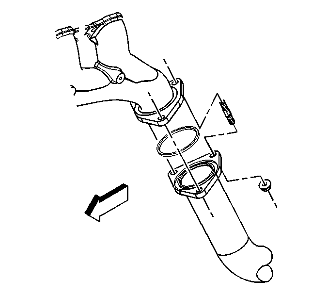
- Remove the exhaust manifold pipe nuts.
- Lower the vehicle.
- Remove the spark plugs. Refer to Spark Plug Replacement .
- Remove the engine coolant temperature (ECT) sensor. Refer to Engine Coolant Temperature Sensor Replacement .
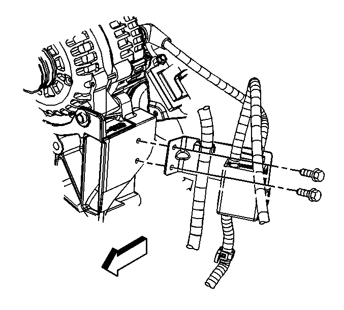
- Remove the junction block bracket bolts.
- Reposition the junction block.
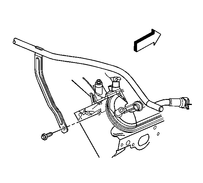
- Remove the secondary air injection (AIR) check valve pipe (crossover) bolt.
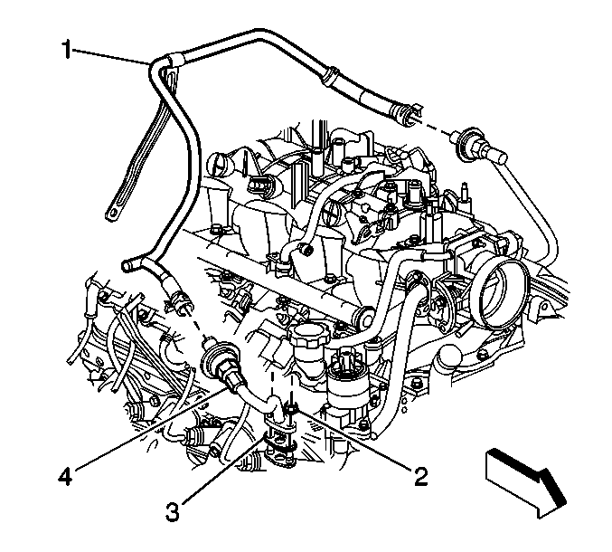
- Reposition the AIR check valve pipe (crossover) hose spring clamps.
- Remove the AIR check valve pipe (crossover) (1) from both check valves.
- Remove the AIR check valve pipe nuts, pipe (with check valve), and gasket from the left exhaust manifold.
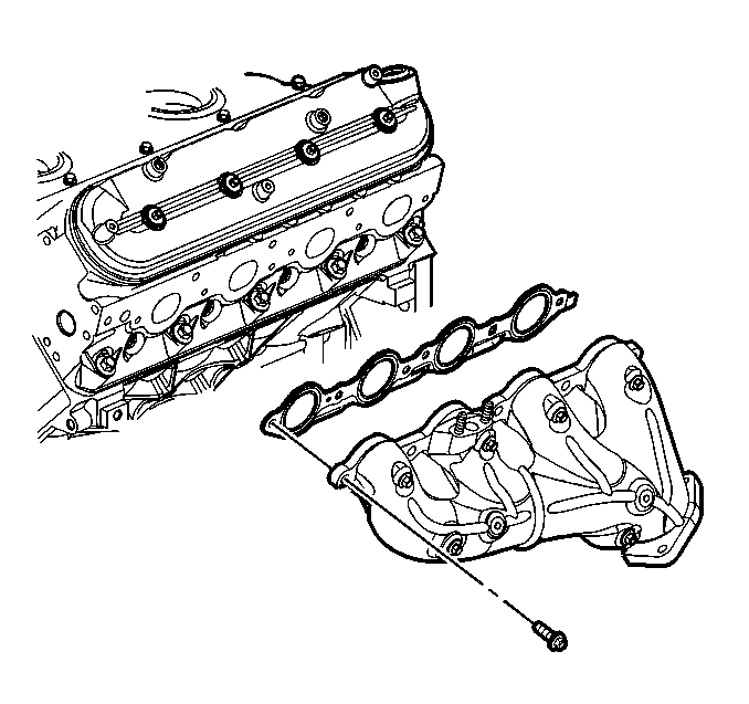
- Remove the exhaust manifold bolts, manifold, and gasket.
- Discard the gasket and bolts.
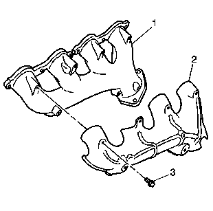
- If necessary, remove the heat shield bolts (3), and shield (2) from the exhaust manifold (1).
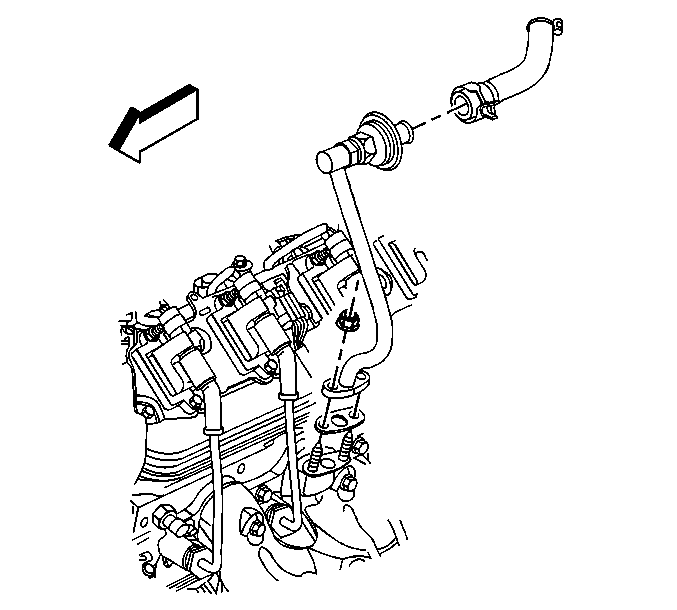
Important: Do not remove the check valve from the AIR pipe unless valve replacement is required.
Installation Procedure
- Install the exhaust manifold to the cylinder head. Refer to Exhaust Manifold Installation - Left Side .
- Install a NEW AIR check valve pipe gasket, the nuts, and pipe (with check valve) to the left exhaust manifold.
- Install the AIR check valve pipe (crossover) (1) to the check valves.
- Position the AIR check valve pipe (crossover) hose spring clamps.
- Install the AIR check valve pipe (crossover) bolt.
- Position the junction block to the generator bracket.
- Install the junction block bracket bolts.
- Install the ECT sensor. Refer to Engine Coolant Temperature Sensor Replacement .
- Install the spark plugs. Refer to Spark Plug Replacement .
- Raise the vehicle.
- Install the exhaust manifold pipe nuts.
- Lower the vehicle.
Notice: Refer to Fastener Notice in the Preface section.

Tighten
Tighten the AIR check valve pipe nuts to 25 N·m (18 lb ft).


Tighten
Tighten the AIR check valve pipe nuts to 50 N·m (37 lb ft).

Tighten
Tighten the junction block bracket bolts to 9 N·m (80 lb in).

Tighten
Tighten the exhaust manifold pipe nuts to 50 N·m (37 lb ft).
Exhaust Manifold Replacement - Left Side 4.3 L
Removal Procedure
- Raise the vehicle. Refer to Lifting and Jacking the Vehicle .
- Remove the exhaust manifold pipe nuts.
- Lower the vehicle.
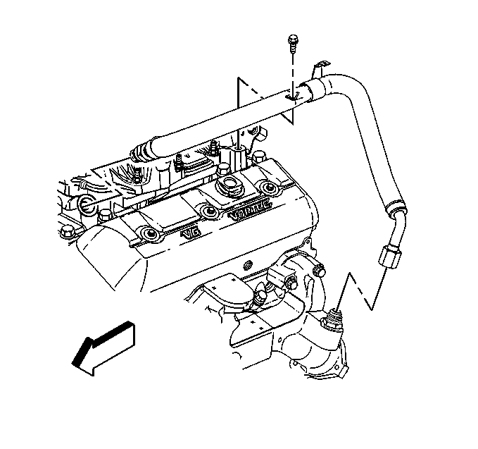
- Remove the secondary air injection (AIR) pipe assembly, if equipped from the exhaust manifold.
- Disconnect the spark plug wires from the spark plugs.
- Remove the spark plug wires from the spark plug wire retainers.
- Disconnect the exhaust gas recirculation (EGR) valve inlet pipe from the exhaust manifold.
- Disconnect the engine coolant temperature (ECT) sensor electrical connector.
- Remove the exhaust manifold bolts and the stud.
- Remove the exhaust manifold.
- Remove and discard the exhaust manifold gaskets.
- Remove the bolts and the spark plug wire shield, if necessary.
- Clean all gasket surfaces.

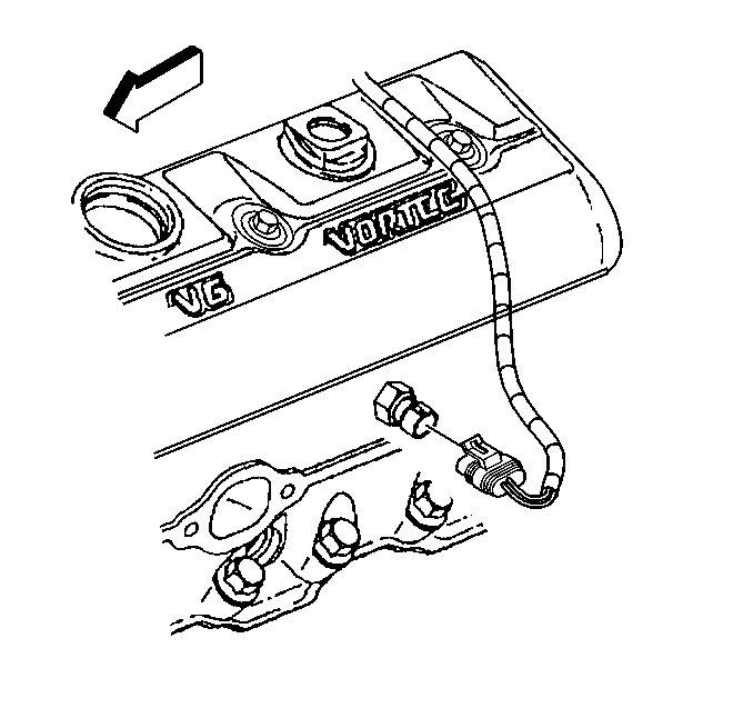
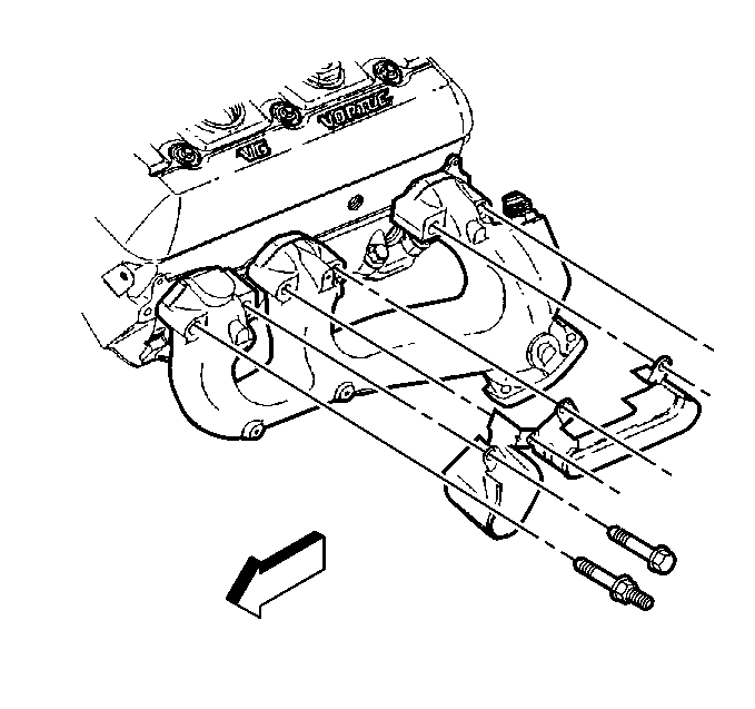
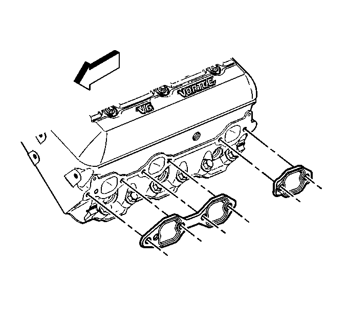
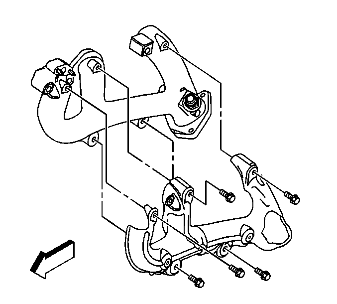
Installation Procedure
- Install the spark plug wire shields, if removed.
- Install the spark plug wire shield bolts.
- Install the NEW exhaust manifold gaskets to the exhaust manifold.
- Ensure that the exhaust manifold bolts and stud are held in place by the tabs on the exhaust manifold gaskets.
- Install the exhaust manifold.
- If reusing the fasteners, apply threadlock GM P/N 12345493 or equivalent to the threads of the exhaust manifold bolts and stud.
- Install the exhaust manifold bolts and stud.
- Tighten the exhaust manifold bolts and stud on the first pass to 15 N·m (11 lb ft).
- Tighten the exhaust manifold bolts and stud on the final pass to 30 N·m (22 lb ft).
- Connect the EGR valve inlet pipe to the exhaust manifold.
- Connect the ECT sensor electrical connector.
- Install the spark plug wires to the spark plug wire retainers.
- Connect the spark plug wires to the spark plugs.
- Install the AIR pipe assembly to the exhaust manifold.
- Raise the vehicle.
- Connect the exhaust pipe to the exhaust manifold.
- Install NEW exhaust manifold pipe seals to the exhaust manifolds.
- Install the left exhaust manifold pipe nuts until snug.
- Tighten the exhaust manifold pipe nuts.
- Lower the vehicle.

Notice: Use the correct fastener in the correct location. Replacement fasteners must be the correct part number for that application. Fasteners requiring replacement or fasteners requiring the use of thread locking compound or sealant are identified in the service procedure. Do not use paints, lubricants, or corrosion inhibitors on fasteners or fastener joint surfaces unless specified. These coatings affect fastener torque and joint clamping force and may damage the fastener. Use the correct tightening sequence and specifications when installing fasteners in order to avoid damage to parts and systems.
Tighten
Tighten the spark plug wire shield bolts to 9 N·m (80 lb in).
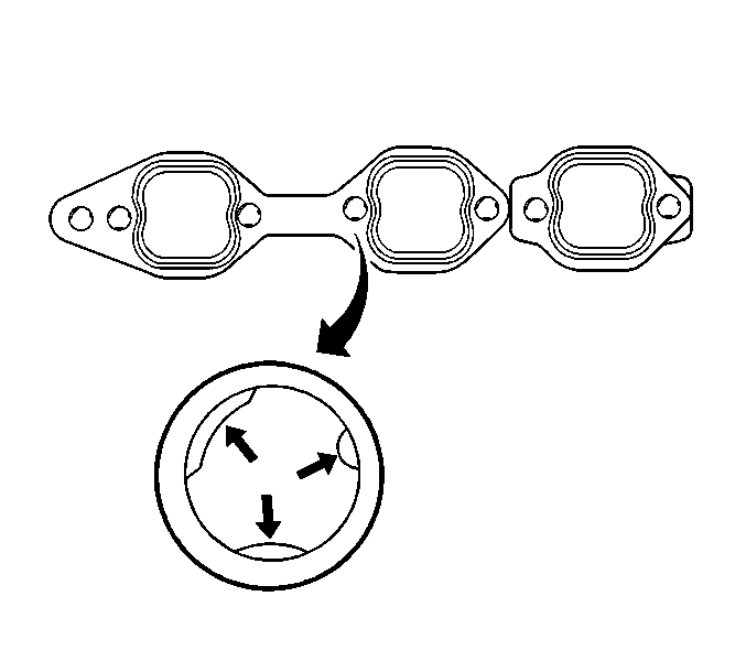
Important: To assist in installing the exhaust manifold to the engine, the tabs on a NEW exhaust manifold gasket will hold the gasket and bolts in place.

Tighten

Tighten
Tighten the EGR valve inlet pipe nut to 30 N·m (22 lb ft).

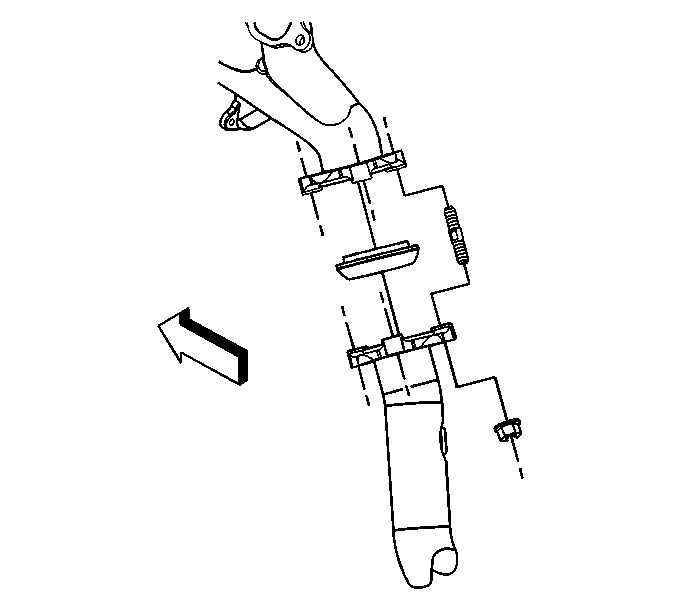
Tighten
Tighten the exhaust manifold pipe nuts to 50 N·m (37 lb ft).
Exhaust Manifold Replacement - Left Side 6.6 L
Removal Procedure
- Raise the vehicle. Refer to Lifting and Jacking the Vehicle in General Information.
- Remove the bolts retaining the left exhaust pipe heat shield.
- Move the heat shield to the side in order to access the exhaust pipe to manifold bolts.
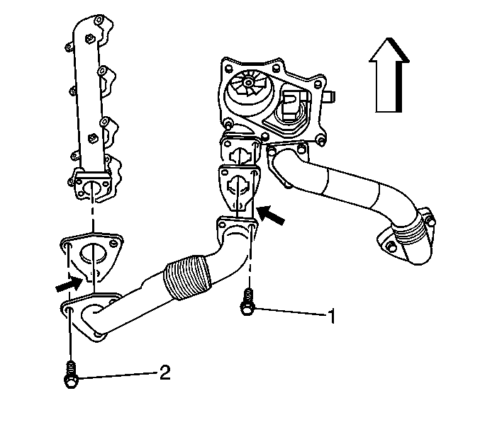
- Remove the left exhaust pipe to exhaust manifold bolts (2).
- Lower the vehicle in order to work through the front fender wheelhouse opening.
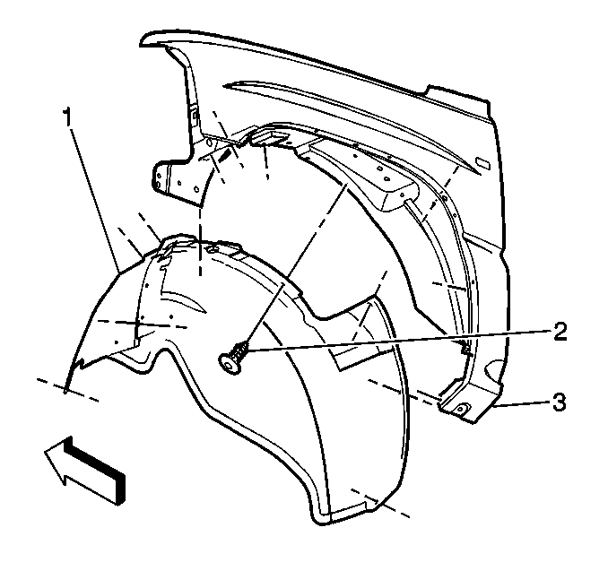
- Remove the left front fender wheelhouse inner panel (1).
- Remove the left front tire and wheel assembly. Refer to Tire and Wheel Removal and Installation in Tires and Wheels.
- Remove the charged air cooler outlet duct from the vehicle. Refer to Charged Air Cooler Hoses/Pipes Replacement in Engine Mechanical 6.6 L.
- Remove the bolts for the exhaust manifold heat shield.
- Remove the exhaust manifold heat shield.
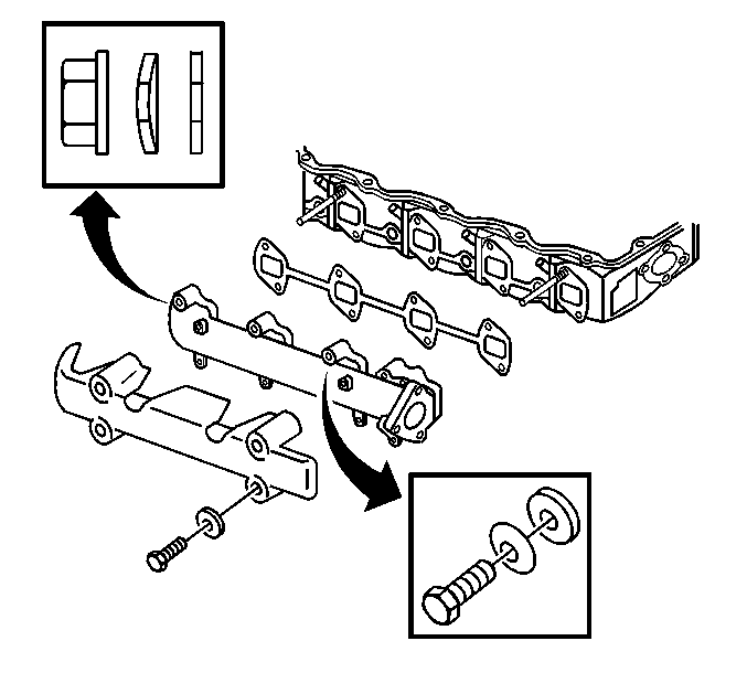
- Remove the 2 nuts and 6 bolts with plain washer and bell view washer from the left exhaust manifold.
- Remove the exhaust manifold.
- Remove the exhaust manifold gasket and discard.
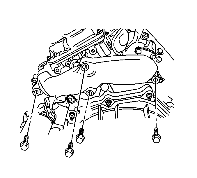
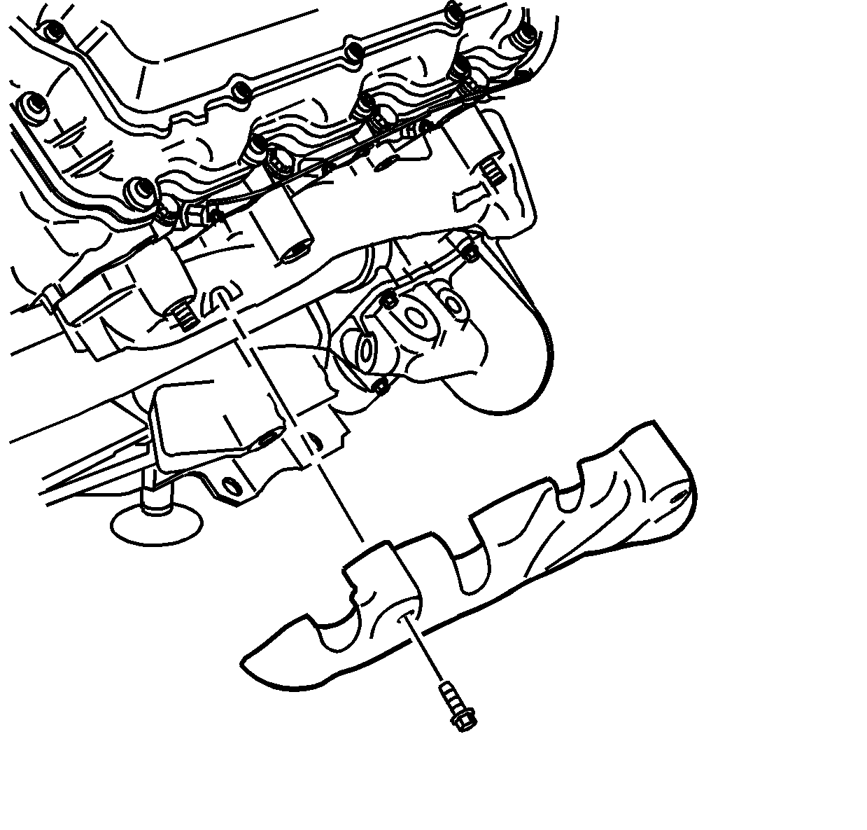
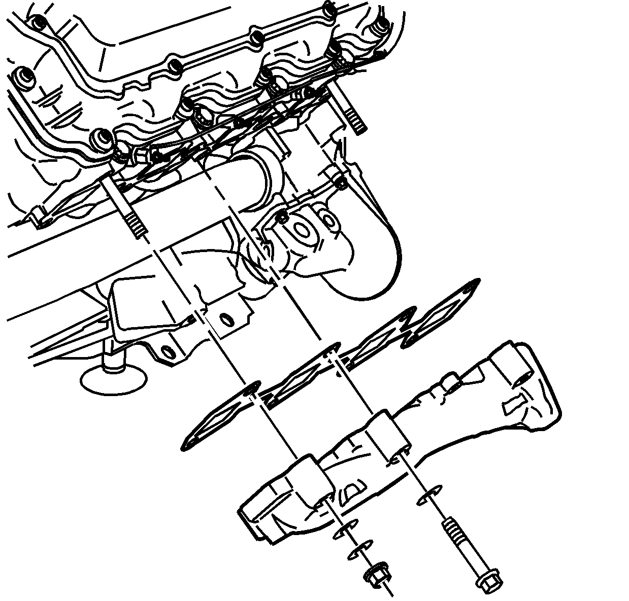
| 12.1. | Remove the manifold from the rear stud. |
| 12.2. | Remove the manifold from the front stud. |
| 12.3. | Slide the manifold out the bottom, past the oil filter. |
Inspection and Repair
- Clean the exhaust manifold.
- Clean the exhaust manifold mating surfaces.
- Inspect the exhaust manifold for cracks.
- Inspect the exhaust manifold mating surfaces for damage.
- Replace the exhaust manifold if any damage is found.
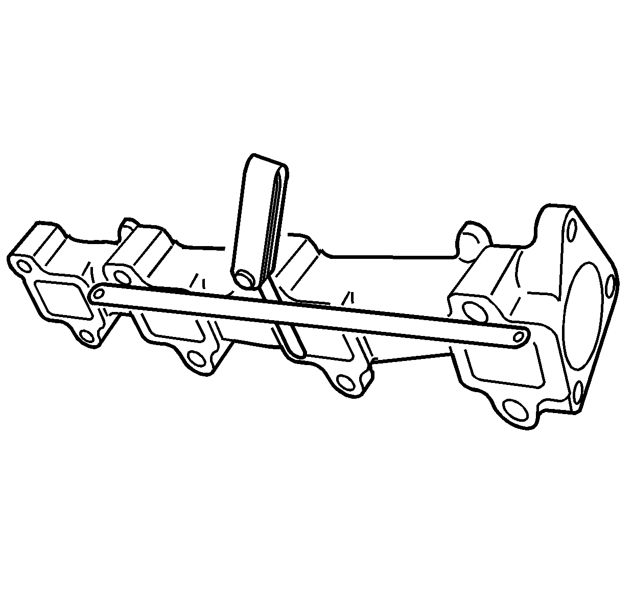
- Measure the exhaust manifold flange for warpage with feeler gauge and a straightedge. Replace the exhaust manifold if the warpage is more than 0.3 mm (0.0118 in).
- Replace the exhaust manifold if warpage is more than the limits.
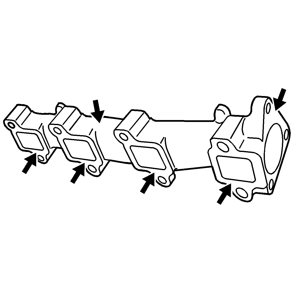
Installation Procedure
- Install the exhaust manifold with gasket to the cylinder head.
- Install the exhaust manifold bolts and nuts with the bell view washers and the plain washers.
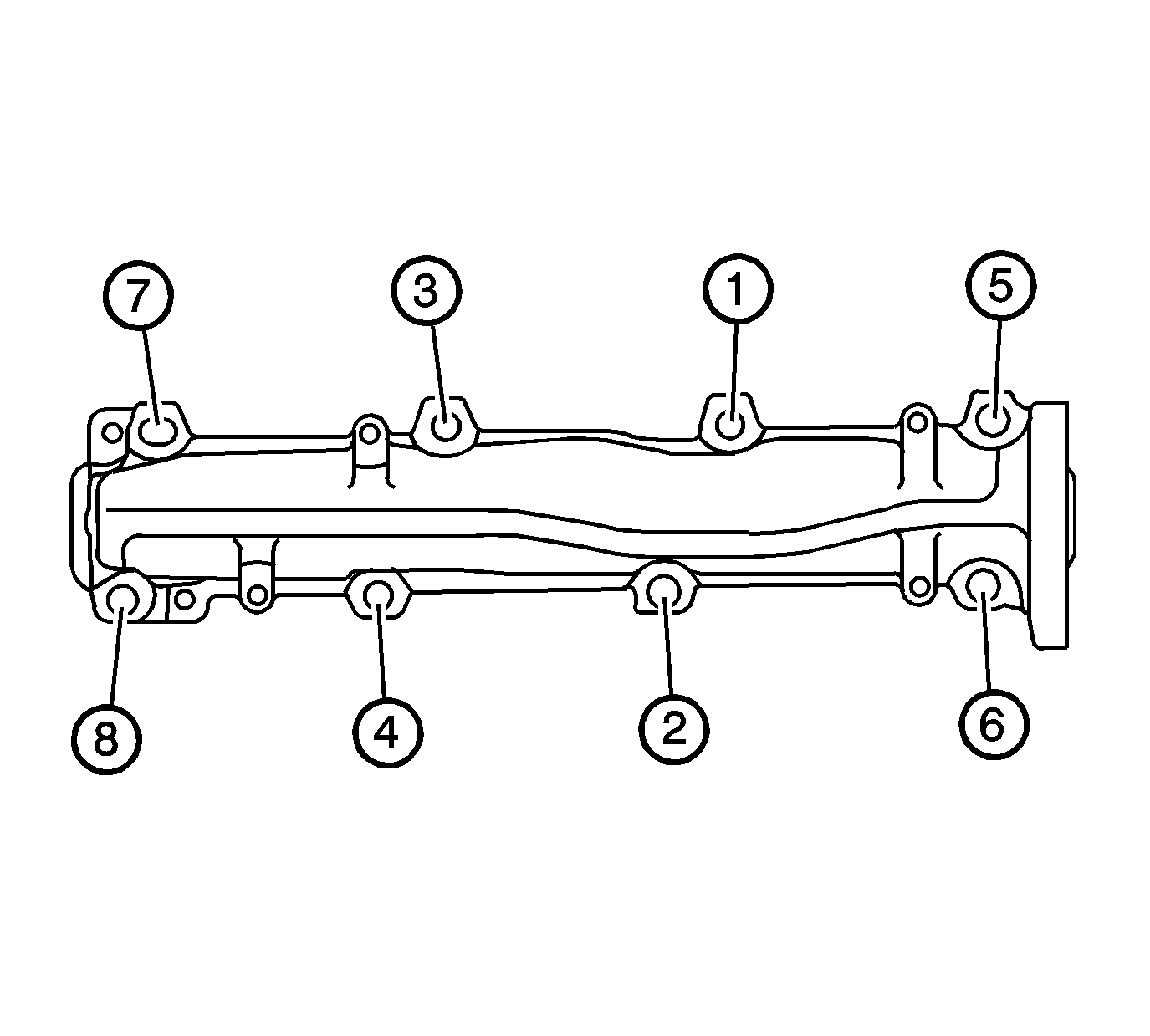
- Use the sequence shown to properly tighten the exhaust manifold bolts.
- Tighten the exhaust manifold nuts and bolts to 34 N·m (25 lb ft) in the proper sequence.
- Tighten the exhaust manifold nuts and bolts again to 34 N·m (25 lb ft) in the proper sequence.
- Install the exhaust manifold heat shield.
- Install the exhaust manifold heat shield bolts.
- Install the exhaust pipe gasket. Align the tab on the gasket to face outward as shown.
- Install the exhaust pipe and the bolts (2) to the exhaust manifold.
- Raise the vehicle.
- Install the exhaust pipe heat shield bolts.
- Install the charged air cooler outlet duct. Refer to Charged Air Cooler Hoses/Pipes Replacement in Engine Mechanical 6.6 L.
- Install the left front tire and wheel assembly. Refer to Tire and Wheel Removal and Installation in Tires and Wheels.
- Install the left front fender wheelhouse inner panel (1).
- Lower the vehicle.
Notice: Refer to Fastener Notice in the Preface section.
Tighten

Tighten
Tighten the exhaust manifold heat shield bolts to 8 N·m (71 lb in).

Tighten
Tighten the exhaust pipe to manifold bolts to 53 N·m (39 lb ft).

Tighten
Tighten the exhaust pipe heat shield bolts to 8 N·m (71 lb in).

Exhaust Manifold Replacement - Left Side 8.1 L Engine
Removal Procedure
- Remove the wheelhouse panel. Refer to Wheelhouse Panel Replacement in Body Front End.
- Remove the secondary air injection (AIR) pipe nut from the fuel rail stud, if equipped.
- Remove the AIR pipe bolts from the exhaust manifold, if equipped.
- Disconnect the AIR pipe from the AIR pump pipe, if equipped.
- Remove the AIR pipe, if equipped.
- Remove and discard the AIR pipe gasket, if equipped.
- Remove the spark plug wires from the spark plugs and ignition coils.
- Remove the spark plugs. Refer to Spark Plug Replacement in Engine Controls - 8.1 L.
- Raise and suitably support the vehicle with safety stands. Refer to Lifting and Jacking the Vehicle in General Information.
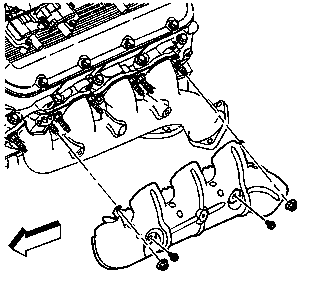
- Remove the exhaust manifold heat shield bolts and nuts.
- Remove the left exhaust manifold heat shield.
- Lower the vehicle.
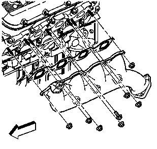
- Remove the exhaust manifold bolt and nuts.
- Remove the exhaust manifold.
- Remove and discard the exhaust manifold gasket.
- Clean and inspect the exhaust manifold. Refer to Exhaust Manifold Cleaning and Inspection in Engine Mechanical - 8.1 L Unit Repair.
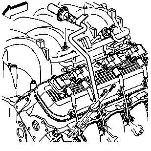
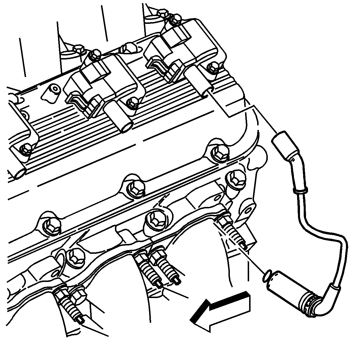
Important: Twist the spark plug boot one-half turn in order to release the boot. Pull on the spark plug boot only. Do not pull on the spark plug wire or the wire could be damaged.
Installation Procedure
- Install a NEW exhaust manifold gasket.
- Install the exhaust manifold.
- Install the exhaust manifold bolt and nuts.
- Raise the vehicle.
- Install the exhaust manifold heat shield.
- Install the exhaust manifold heat shield bolts and nuts.
- Lower the vehicle.
- Install the spark plugs. Refer to Spark Plug Replacement in Engine Controls - 8.1 L.
- Install the spark plug wires to the spark plugs and ignition coils.
- Install a NEW AIR pipe gasket, if equipped.
- Install the AIR pipe, if equipped.
- Connect the AIR pipe from the AIR pump pipe, if equipped.
- Install the AIR pipe bolts to the exhaust manifold, if equipped.
- Install the AIR pipe nut to the fuel rail stud, if equipped.
- Install the wheelhouse panel. Refer to Wheelhouse Panel Replacement in Body Front End.

Notice: Use the correct fastener in the correct location. Replacement fasteners must be the correct part number for that application. Fasteners requiring replacement or fasteners requiring the use of thread locking compound or sealant are identified in the service procedure. Do not use paints, lubricants, or corrosion inhibitors on fasteners or fastener joint surfaces unless specified. These coatings affect fastener torque and joint clamping force and may damage the fastener. Use the correct tightening sequence and specifications when installing fasteners in order to avoid damage to parts and systems.
Tighten
| • | Tighten the exhaust manifold bolt to 35 N·m (26 lb ft). |
| • | Tighten the exhaust manifold nuts to 16 N·m (12 lb ft). |

Tighten
Tighten the heat shield bolts and nuts to 25 N·m (18 lb ft).

Important: Fully install the spark plug wire by pushing on the exposed end of the spark plug boot. Do not push the spark plug wire on to the spark plug by using the metal heat shield.

Tighten
Tighten the AIR pipe bolts to 25 N·m (18 lb ft).
Tighten
Tighten the AIR pipe nut to 12 N·m (106 lb in).
