Exhaust Manifold Replacement - Left Side 4.8L, 5.3L, 6.0L, and 6.2L
Special Tools
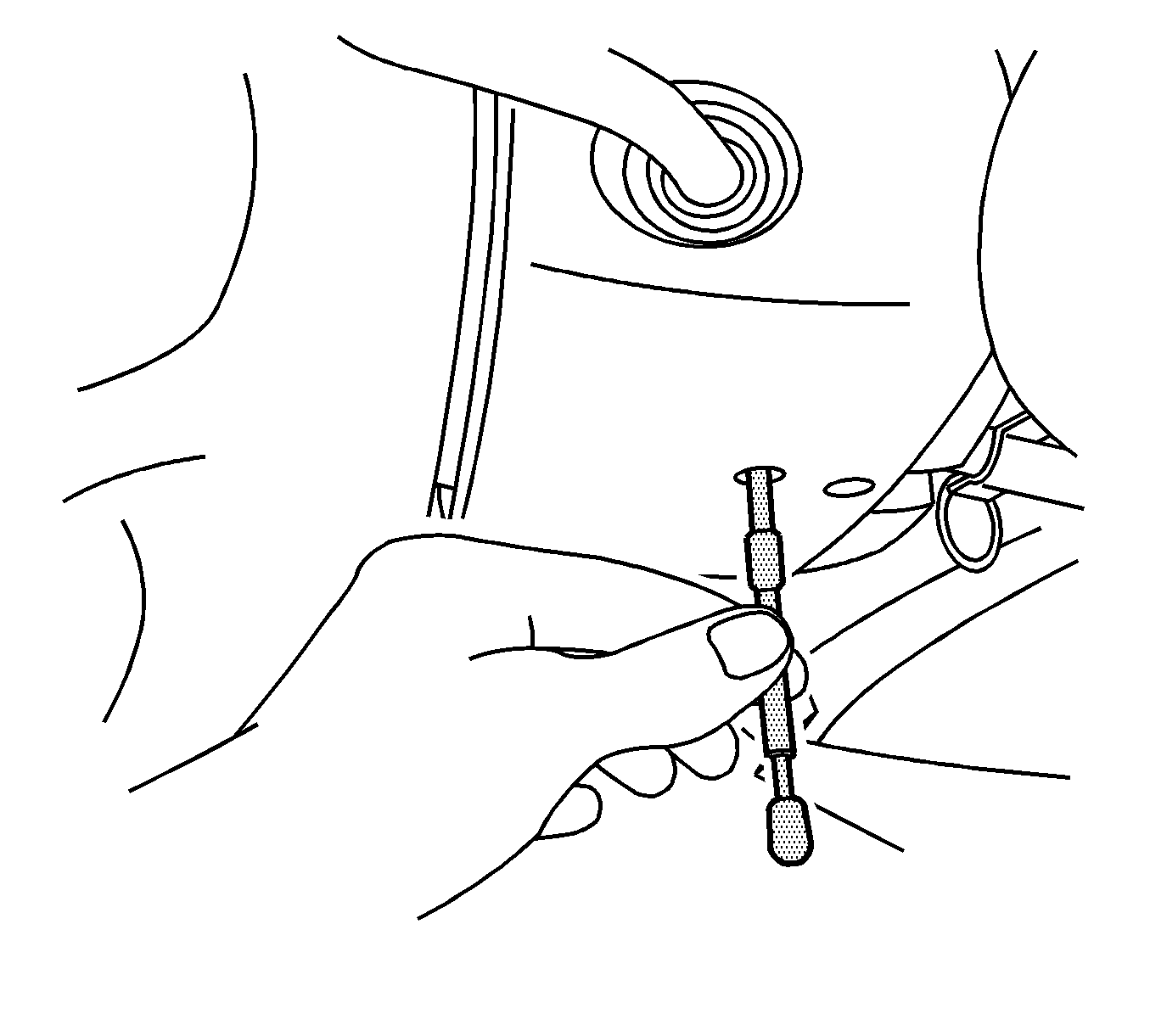
J 42640 Steering Column Anti-Rotation Pin
Removal Procedure
- Install the J 42640 into the steering column lower access hole.
- Remove the left wheelhouse liner. Refer to Front Wheelhouse Liner Replacement - Left Side.
- Fully raise and support the vehicle. Refer to Lifting and Jacking the Vehicle.
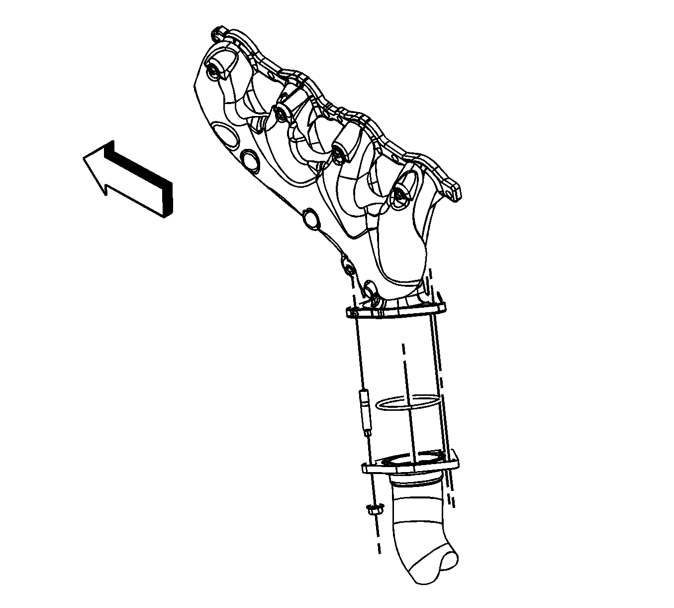
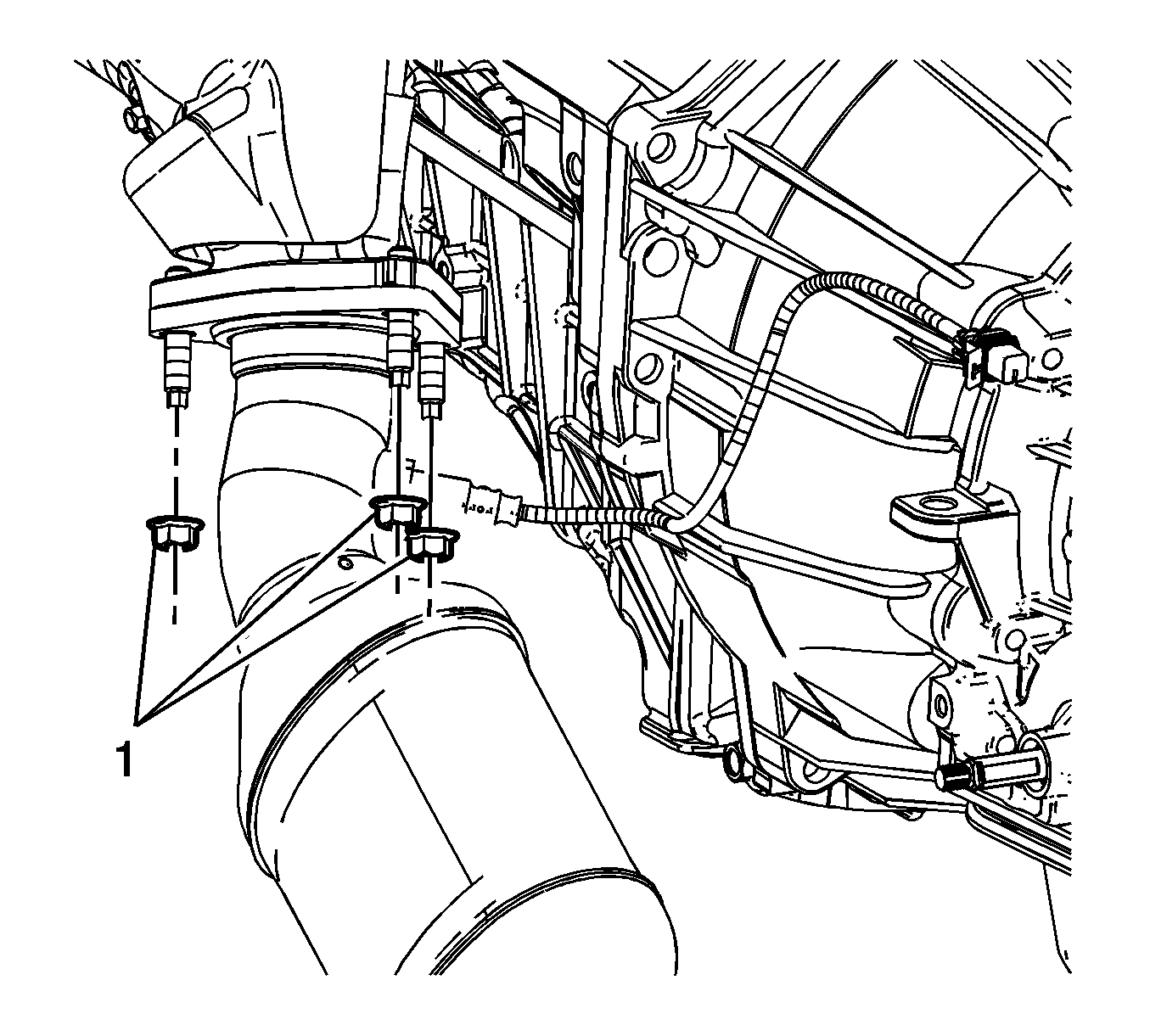
- Remove the catalytic converter to exhaust manifold nuts. (1500 series shown, 2500 series similar).
- Lower the vehicle part way in order to work through the wheel opening.
- Remove the spark plug wires from the spark plugs.
- Remove the spark plug wires from the ignition coils.
- Mark the relationship of the upper intermediate steering shaft to the steering column.
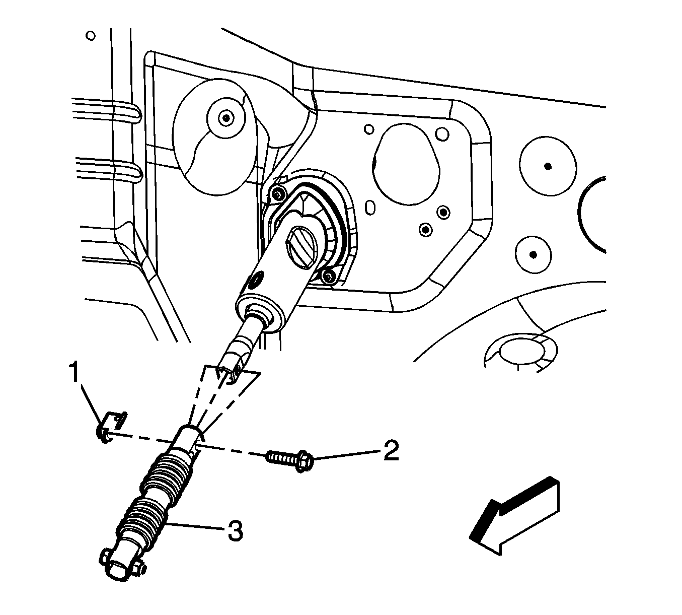
- Remove the steering shaft coupling bolt (2) and nut (1) from the upper intermediate steering shaft.
- Separate the upper intermediate steering shaft (3) from the steering column, position both shafts out of the way.
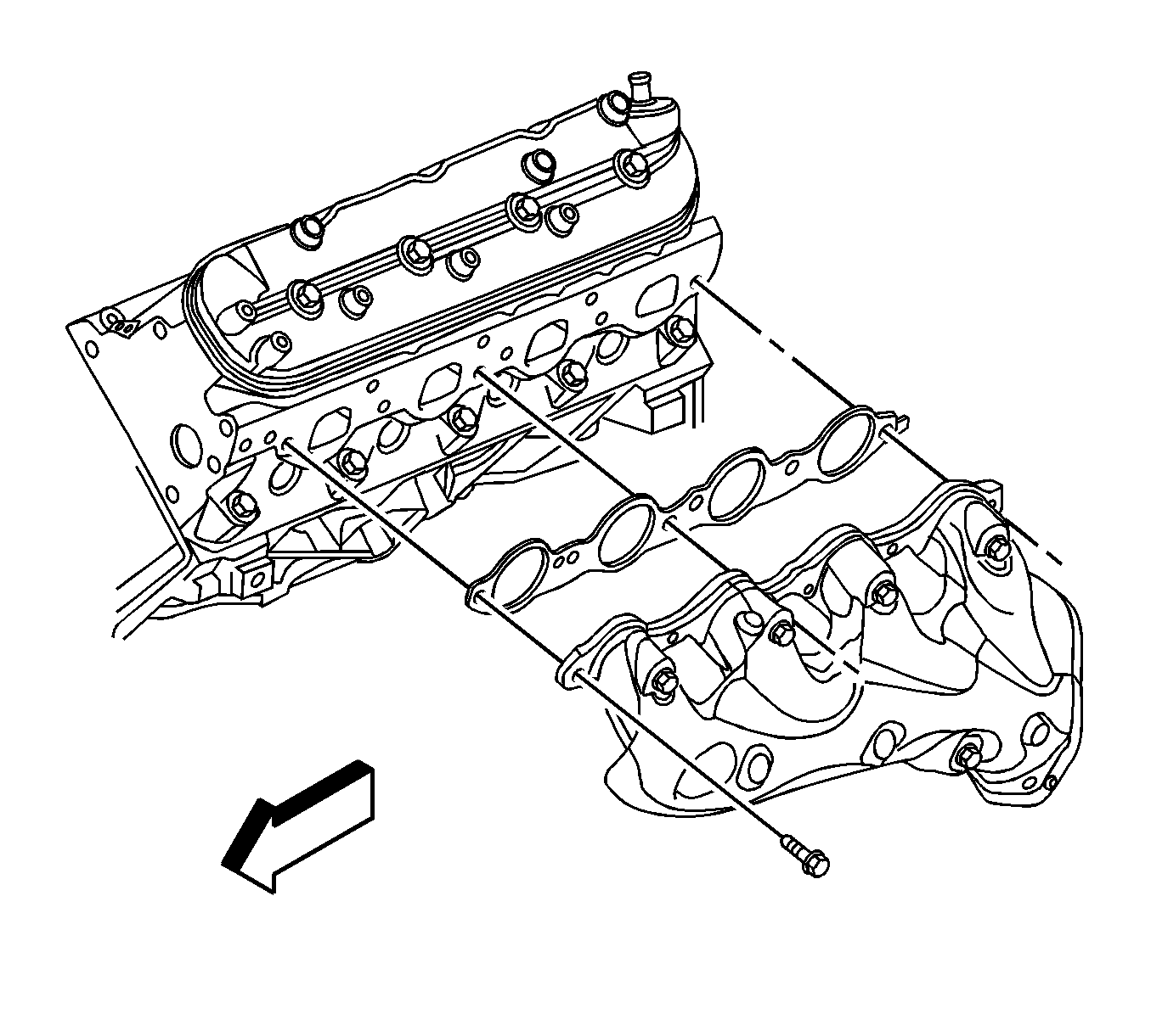
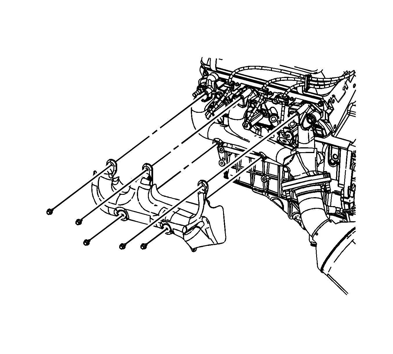
- Remove the exhaust manifold bolts, and exhaust manifold.
- Remove and discard the exhaust manifold gasket.
- Remove and discard the catalytic converter seal.
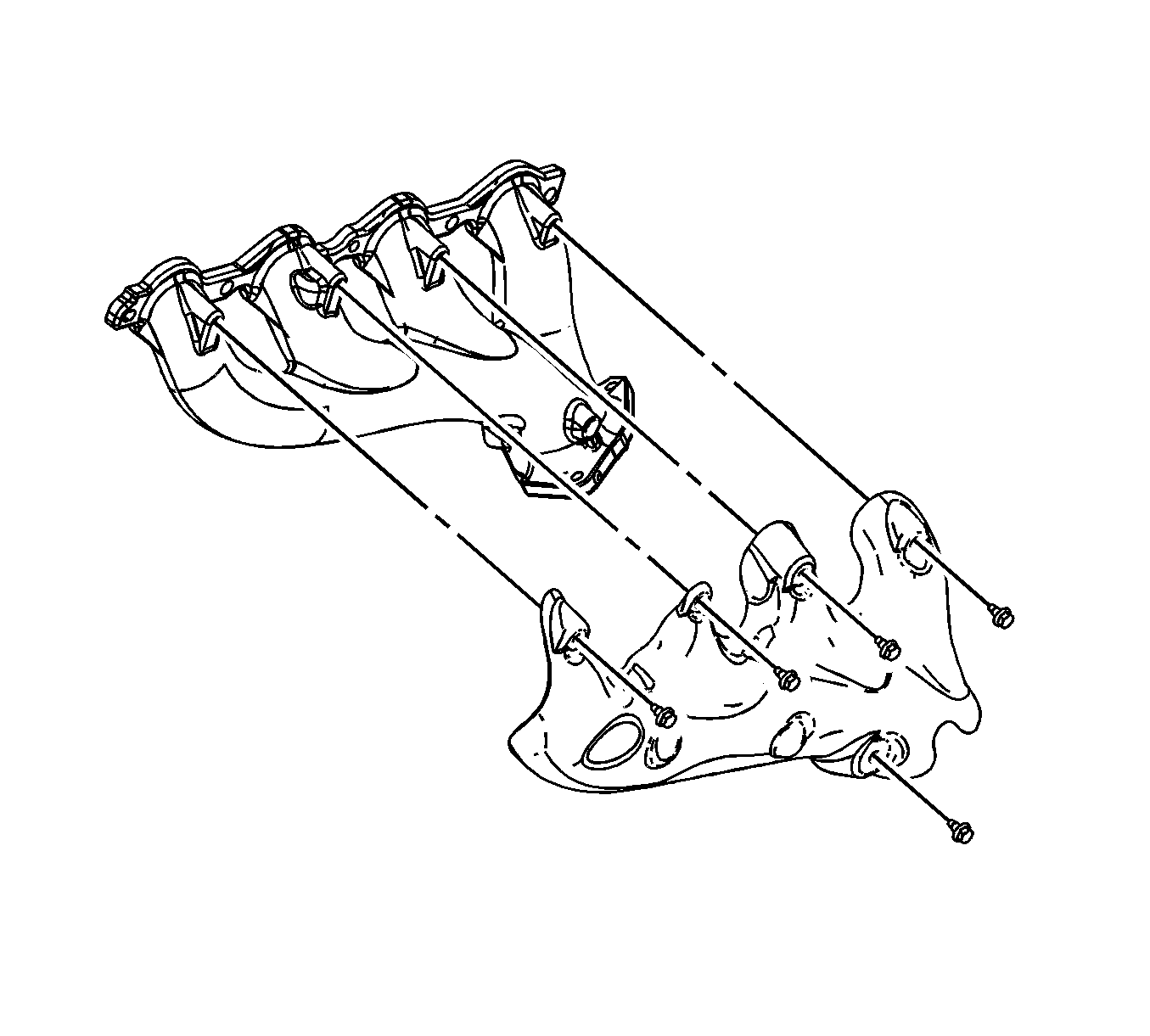
- If replacing the exhaust manifold, remove the exhaust manifold heat shield bolts, and shield from the exhaust manifold.
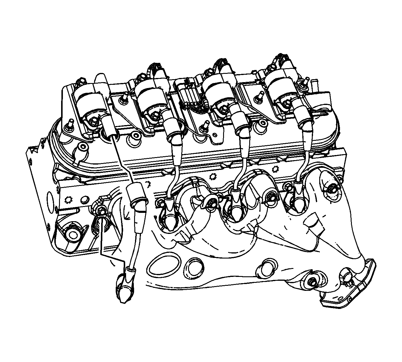
| 6.1. | Twist the spark plug wire boot a 1/2 turn. |
| 6.2. | Pull only on the boot in order to remove the wire from the spark plug. |
| 7.1. | Twist the spark plug wire boot a 1/2 turn. |
| 7.2. | Pull only on the boot in order to remove the wire from the ignition coil. |
Installation Procedure
Note:
• Tighten the exhaust manifold bolts as specified in the service procedure. Improperly installed and/or leaking exhaust manifold gaskets may affect vehicle emissions and/or On-Board Diagnostic (OBD) II system performance. • The cylinder head exhaust manifold bolt hole threads must be clean and free of debris or threadlocking material. • Do not apply sealant to the first 3 threads of the bolt.
- If the exhaust manifold was replaced, position and install the exhaust manifold heat shield, and bolts to the exhaust manifold.
- Clean the threads of the exhaust manifold bolts.
- Apply a 5 mm (0.2 in) wide band of threadlock GM P/N 12345493 (Canadian P/N 10953488), or equivalent to the threads of the exhaust manifold bolts.
- Install a NEW catalytic converter seal to the catalytic converter.
- Position the NEW exhaust manifold gasket and exhaust manifold to the cylinder head.
- Ensure that the exhaust manifold is seated to the catalytic converter.
- Install the exhaust manifold bolts.
- Tighten the bolts a first pass to 15 N·m (11 lb ft). Tighten the exhaust manifold bolts beginning with the center 2 bolts. Alternate from side-to-side, and work toward the outside bolts.
- Tighten the bolts a final pass to 20 N·m (15 lb ft). Tighten the exhaust manifold bolts beginning with the center 2 bolts. Alternate from side-to-side, and work toward the outside bolts.
- Using a flat punch, bend the gasket tab at the rear of the gasket around the cylinder head edge.
- Position and align the marks on the upper intermediate steering shaft and the steering column.
- Install the upper intermediate steering shaft (3) to the steering column.
- Install the steering shaft coupling bolt (2) and nut (1) to the upper intermediate steering shaft.
- Install the spark plug wires to the spark plugs.
- Install the spark plug wires to the ignition coils.
- Inspect the spark plug wires for proper installation.
- Fully raise and support the vehicle.
- Install the catalytic converter to exhaust manifold nuts. (1500 series shown, 2500 series similar).
- Partially lower the vehicle.
- Install the left wheelhouse liner. Refer to Front Wheelhouse Liner Replacement - Left Side.
- Remove the J 42640 from the steering column lower access hole.
Caution: Refer to Fastener Caution in the Preface section.

Tighten
Tighten the bolts to 9 N·m (80 lb in).

Tighten

Tighten
Tighten the bolt/nut to 50 N·m (37 lb ft).

| 14.1. | Push sideways on each boot in order to inspect the seating. |
| 14.2. | Reinstall any loose boot. |

Tighten
Tighten the nuts to 50 N·m (37 lb ft).

Exhaust Manifold Replacement - Left Side 6.6L
Removal Procedure
- Remove the charge air cooler inlet pipe. Refer to Charge Air Cooler Inlet Pipe Replacement.
- Remove the wheelhouse liner. Refer to Front Wheelhouse Liner Replacement - Right Side.
- Perform the following steps working through the wheelhouse opening.
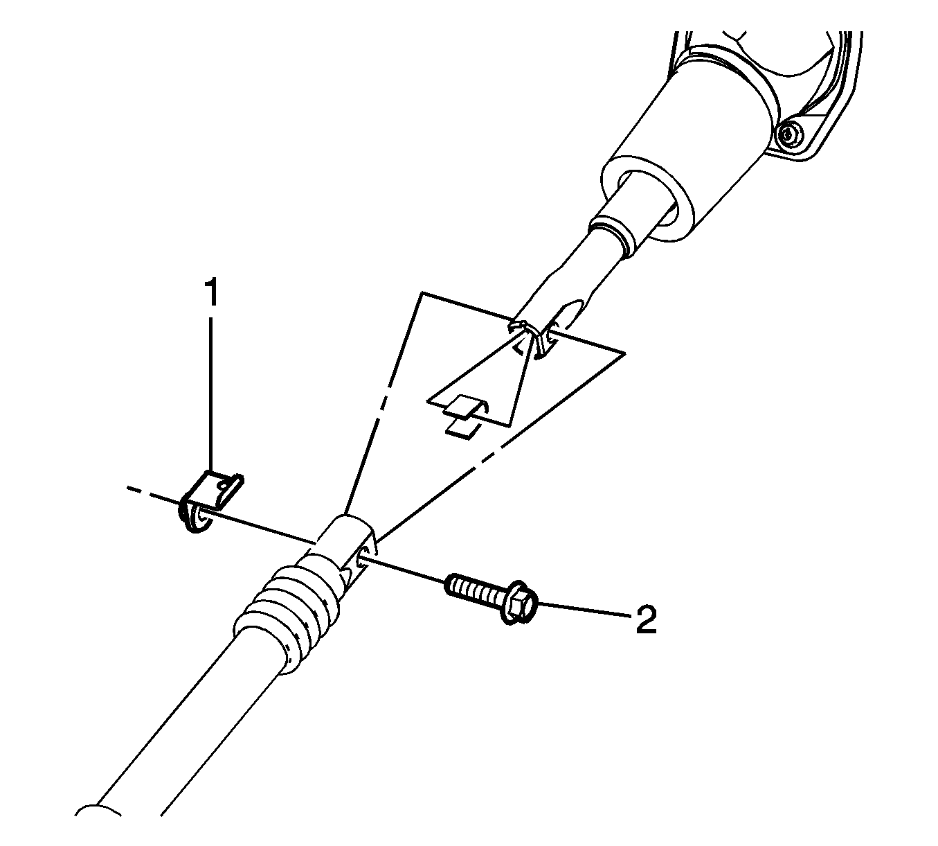
- Remove the steering coupling nut (1) and bolt (2) at the upper intermediate steering shaft.
- Separate the steering shaft coupling from the intermediate shaft.
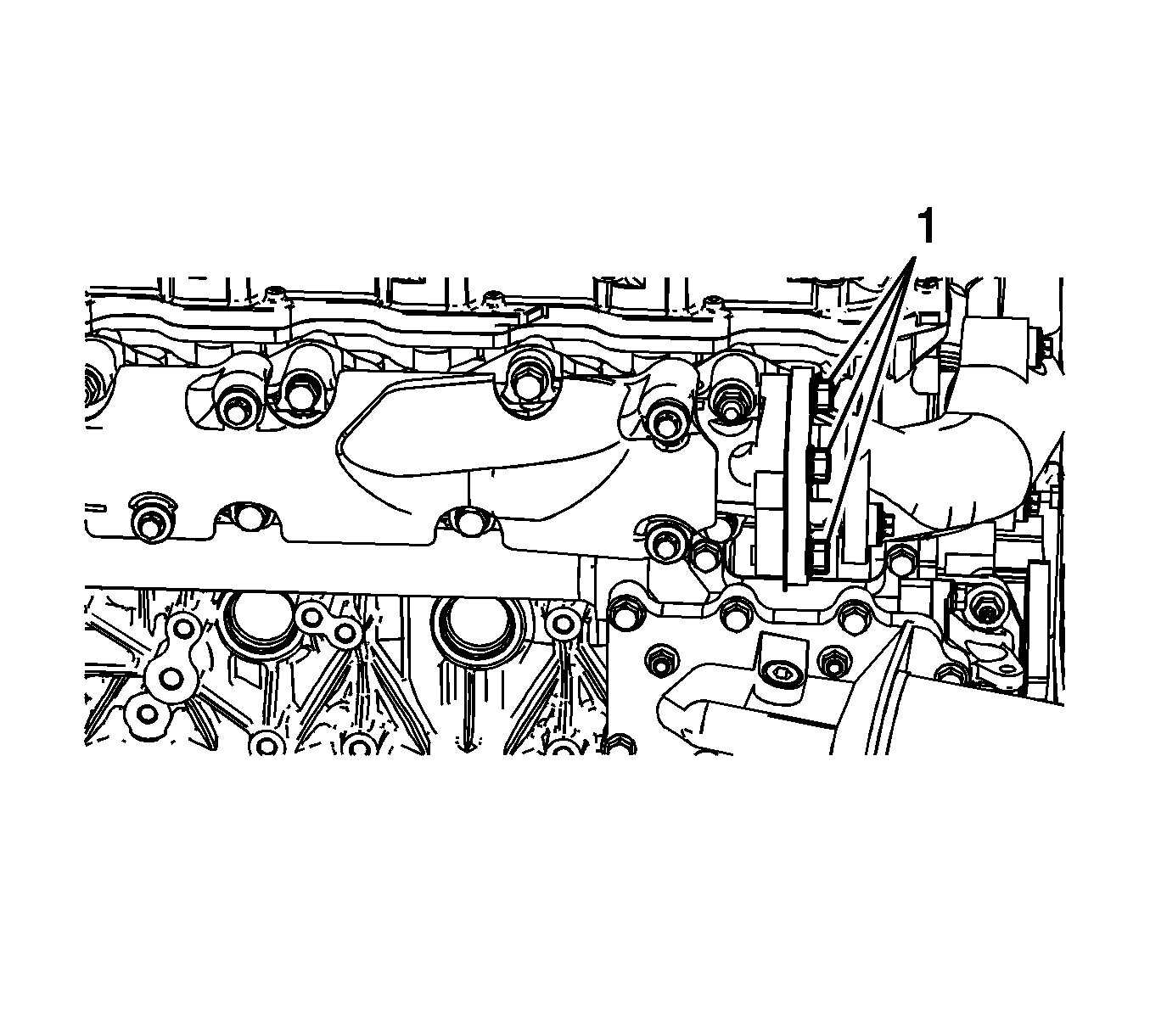
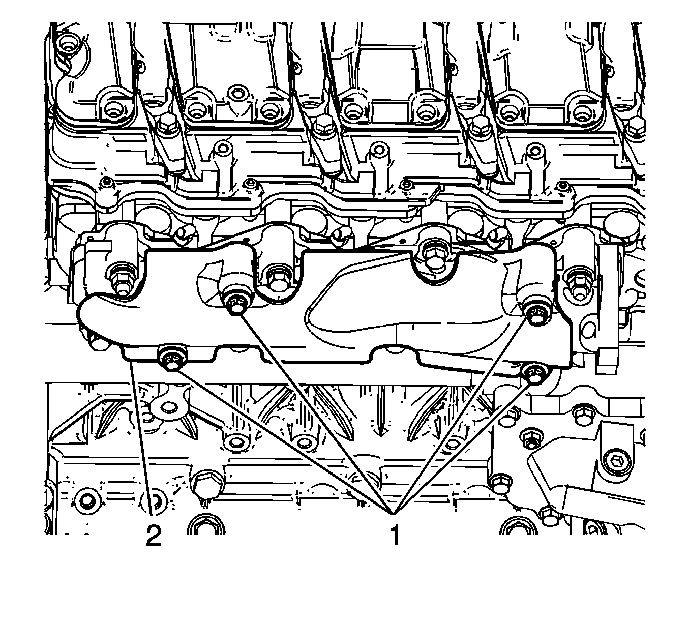
- Remove the exhaust pipe to exhaust manifold bolts (1).
- Remove the exhaust manifold heat shield bolts (1) and shield (2).
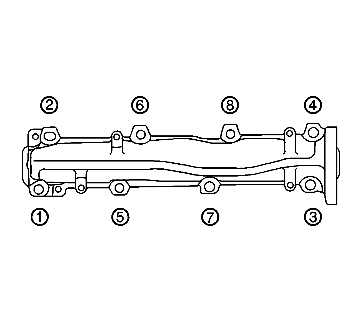
- Remove the exhaust manifold bolts and nuts in the sequence shown.
- Remove the exhaust manifold and gasket. Discard the gasket.
Installation Procedure
- Install the a NEW exhaust manifold gasket onto the manifold studs.
- Position a NEW exhaust pipe gasket between the exhaust manifold and exhaust pipe. Align the tab on the gasket to face outward.
- Install the exhaust manifold onto the studs.
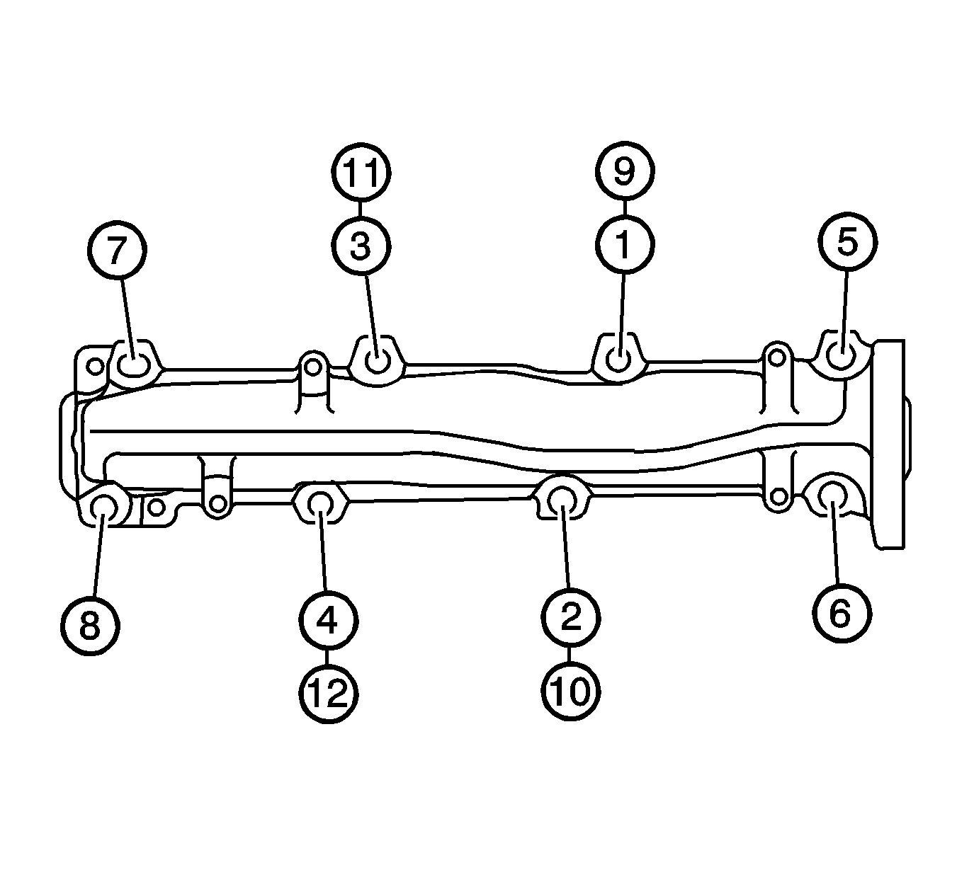
- Install and tighten the exhaust manifold bolts and nuts in the sequence shown to 57 N·m (42 lb ft).
- Tighten the 4 center bolts/nuts an additional pass to 57 N·m (42 lb ft)
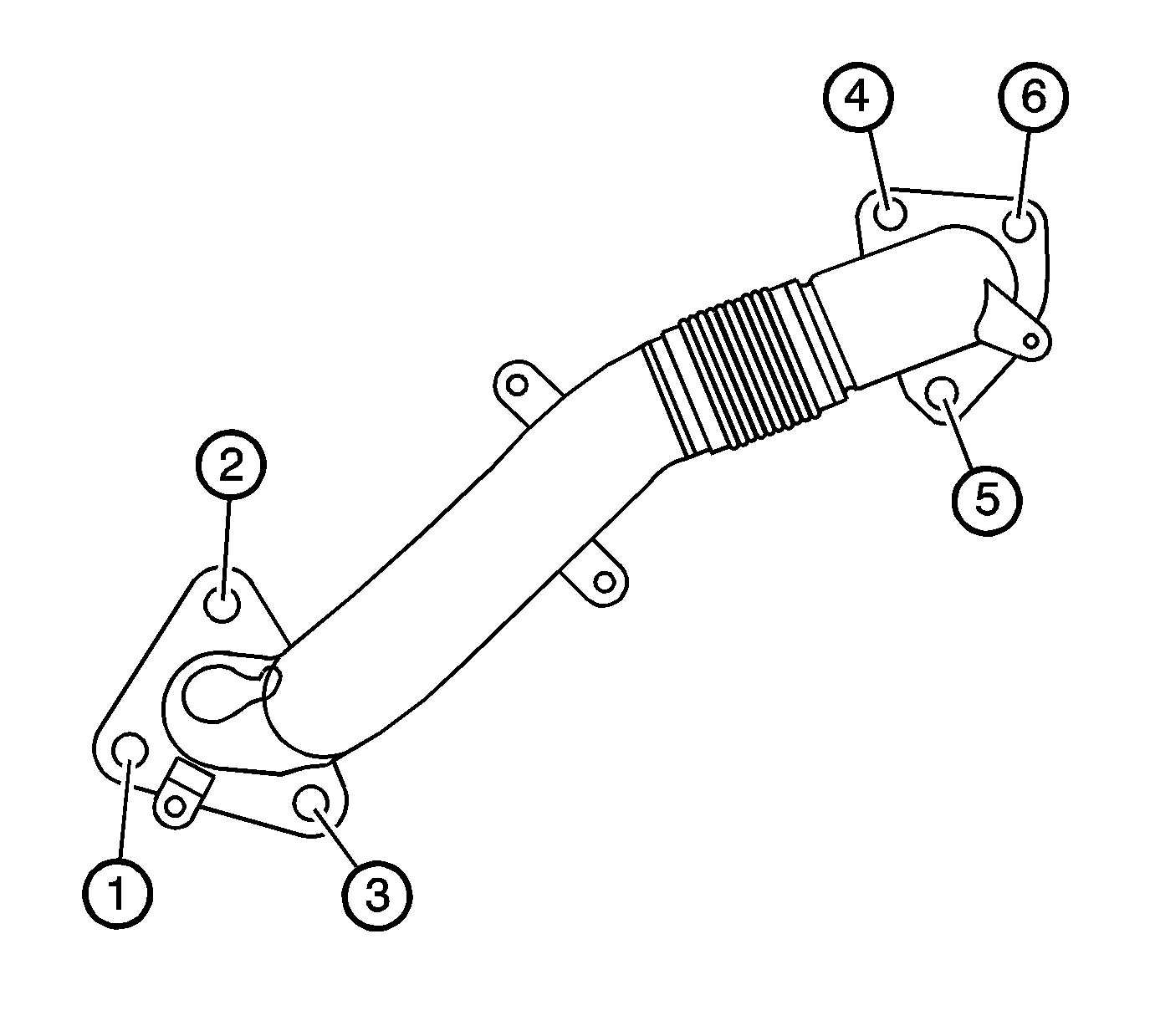
- Install and tighten the exhaust pipe to exhaust manifold bolts in the sequence shown (1, 2, and 3) to 53 N·m (39 lb ft).
- Position the exhaust manifold heat shield (2) to the manifold and install the bolts (1) and tighten to 10 N·m (89 lb in).
- Install the steering shaft coupling to the intermediate shaft.
- Install the steering shaft coupling nut (1) and bolt (2) at the steering shaft coupling and tighten to 50 N·m (37 lb in).
- Install the wheelhouse liner. Refer to Front Wheelhouse Liner Replacement - Right Side.
- Remove the charge air cooler inlet pipe. Refer to Charge Air Cooler Inlet Pipe Replacement.
- Lower the vehicle.
Caution: Refer to Fastener Caution in the Preface section.


Exhaust Manifold Replacement - Left Side 4.3L
Removal Procedure
- Raise and suitably support the vehicle. Refer to Lifting and Jacking the Vehicle.
- Remove the catalytic converter to exhaust manifold nuts (1).
- Lower the vehicle.
- Remove the exhaust manifold heat shield bolts and shield.
- Remove the spark plugs. Refer to Spark Plug Replacement.
- Reposition the spark plug wires out of the way, if necessary.
- Remove the exhaust manifold bolts and stud.
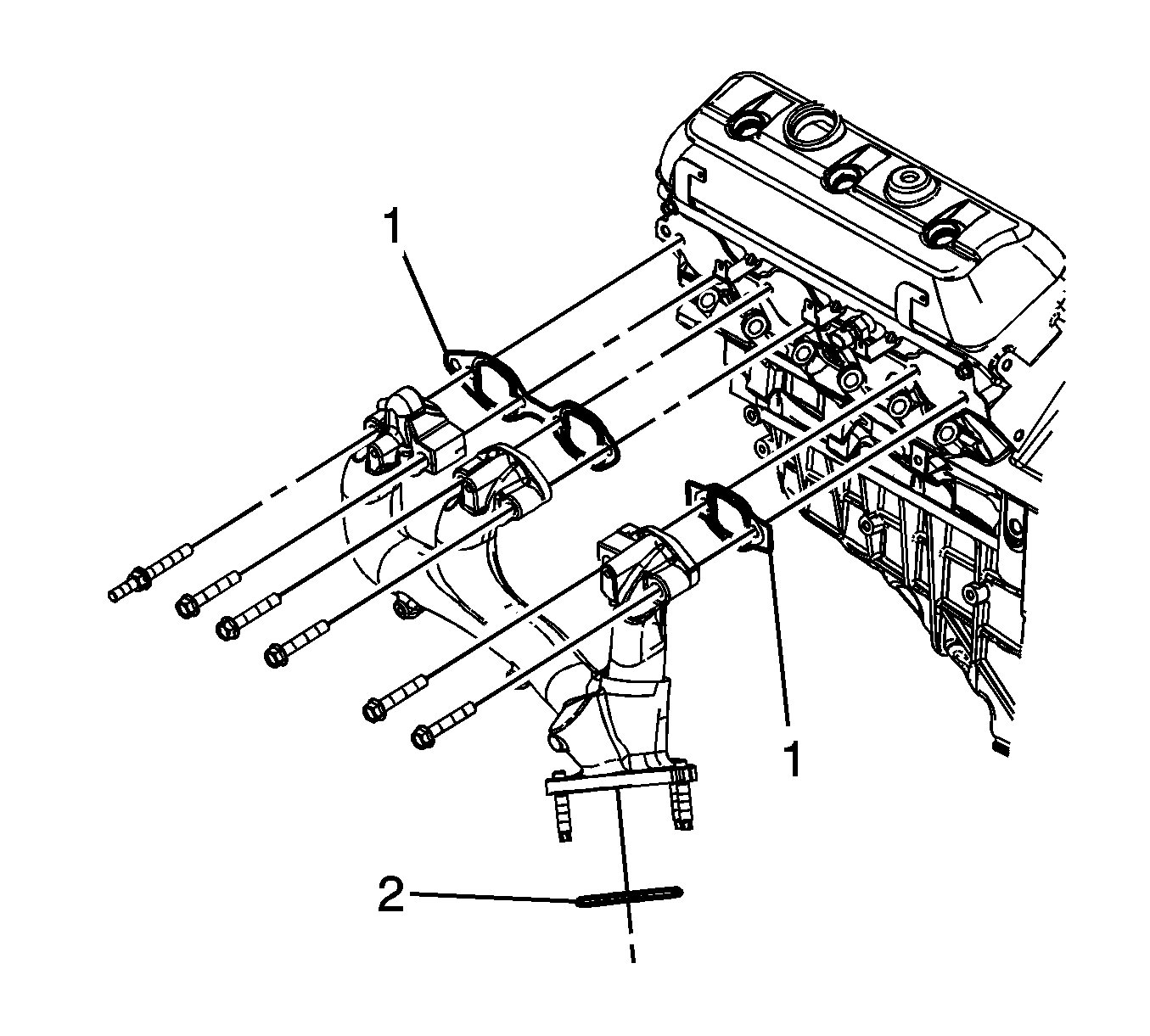
- Remove the exhaust manifold and gaskets (1). Discard the gaskets.
- Remove the exhaust manifold to catalytic converter seal (2). Discard the seal.
Installation Procedure
- Install a NEW exhaust manifold to catalytic converter seal (2) into the relief in the catalytic converter.
- Place the exhaust manifold into position and install the manifold studs to the catalytic converter.
- Place the NEW exhaust manifold gaskets (1) between the manifold and the cylinder head.
- Install the exhaust manifold bolts and stud.
- Install the spark plugs. Refer to Spark Plug Replacement.
- Position the exhaust manifold heat shield to the manifold and install the bolts.
- Raise and support the vehicle.
- Install the catalytic converter to exhaust manifold nuts (1).
- Lower the vehicle.

Caution: Refer to Fastener Caution in the Preface section.
Tighten
Tighten the bolts/stud to 30 N·m (22 lb ft).

Tighten
Tighten the bolts to 9 N·m (80 lb in).

Tighten
Tighten the nuts to 50 N·m (37 lb ft).
