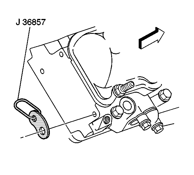
- Install
the J 36857
and a length of chain,
to the right cylinder head rear corner and left cylinder head front corner.
- Install a lifting device to the engine.
- Remove the engine from the engine stand.
Notice: Use the correct fastener in the correct location. Replacement fasteners
must be the correct part number for that application. Fasteners requiring
replacement or fasteners requiring the use of thread locking compound or sealant
are identified in the service procedure. Do not use paints, lubricants, or
corrosion inhibitors on fasteners or fastener joint surfaces unless specified.
These coatings affect fastener torque and joint clamping force and may damage
the fastener. Use the correct tightening sequence and specifications when
installing fasteners in order to avoid damage to parts and systems.
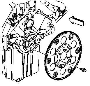
- Install the flywheel to the crankshaft.
Tighten
| • | Tighten the flywheel bolts to 80 N·m (59 lb ft)
a first pass. |
| • | Tighten the flywheel bolts to 100 N·m (74 lb ft)
a final pass. |
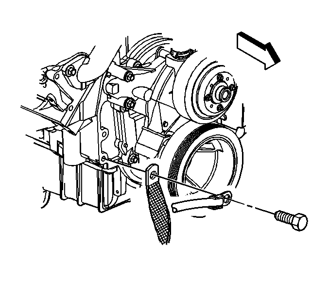
- Install the engine oil cooler lines to the retaining brackets.
- Install the engine to the vehicle.

- Install the transmission and bolts.
Tighten
Tighten the transmission bolts to 47 N·m (34 lb ft).
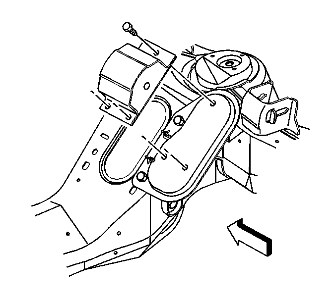
- Install the right engine mount bolts.
Tighten
Tighten the engine mount bolts to 58 N·m (40 lb ft).
- Install the left engine mount bolts.
Tighten
Tighten the engine mount bolts to 58 N·m (40 lb ft).
- Remove the engine lifting device.
- Raise and suitably support the vehicle. Refer to
Lifting and Jacking the Vehicle
in General Information.

- Align
the torque converter and flywheel marks.
- Install the torque converter bolts.
Tighten
Tighten the torque converter bolts to 63 N·m (46 lb ft).

- Install the transmission cover and bolts.
Tighten
Tighten the transmission cover bolts to 33 N·m (24 lb ft).
- Connect the catalytic converter from the exhaust manifolds. Refer to
Catalytic Converter Replacement
in Engine Exhaust.
- Install the starter motor. Refer to
Starter Motor Replacement
in Engine Electrical.
- Untie the engine wiring harness and position.
- Connect the engine wiring harness connectors to the right side of the
engine.
- Connect the engine wiring harness connectors to the left side of the
engine.
- Install the vacuum lines to the engine, as required.
- Connect the TAC module electrical connectors.
- Position the ground straps to the engine
block.
- Install the ground strap bolt.
Tighten
Tighten the ground strap bolt to 25 N·m (18 lb ft).
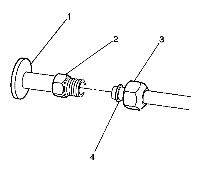
- Connect the fuel lines to the fuel rail.
- Install the generator bracket. Refer to
Generator Bracket Replacement
in Engine Electrical.
- Install the power steering pump. Refer to
Power Steering Pump Replacement
in Power Steering System.
- Install the A/C compressor. Refer to
Air Conditioning Compressor Replacement
in Heating, Ventilation, and Air Conditioning.
- Install the engine oil level indicator tube. Refer to
Oil Level Indicator and Tube Replacement
.
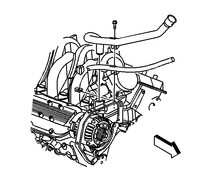
- Install the oil fill tube and upper transmission
fluid indicator tube.
- Install the oil fill tube bolt.
Tighten
Tighten the oil fill tube bolt to 12 N·m (106 lb in).
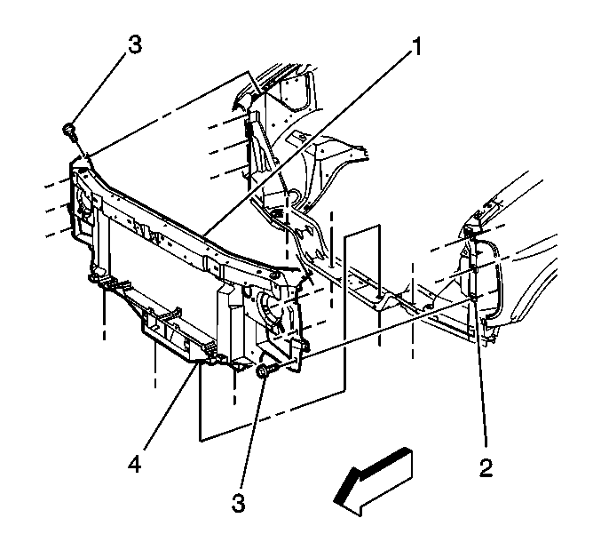
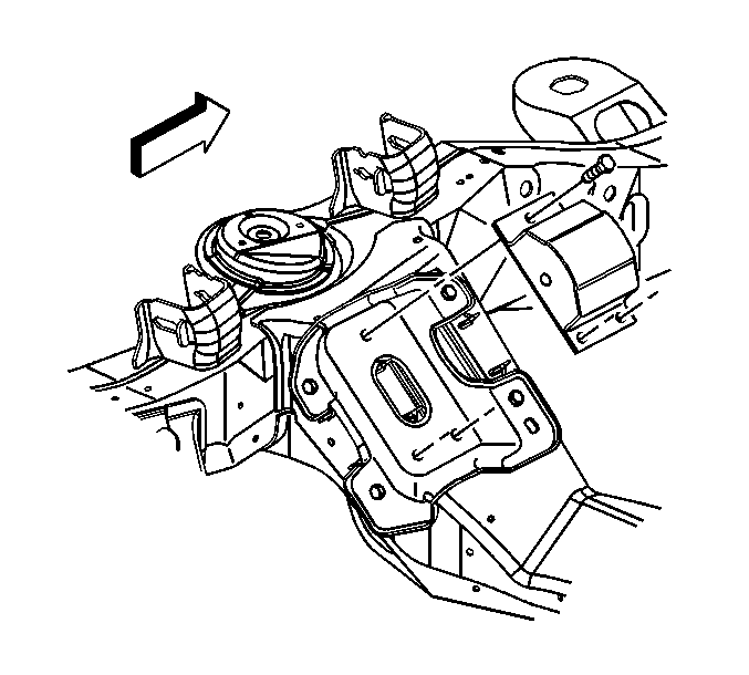
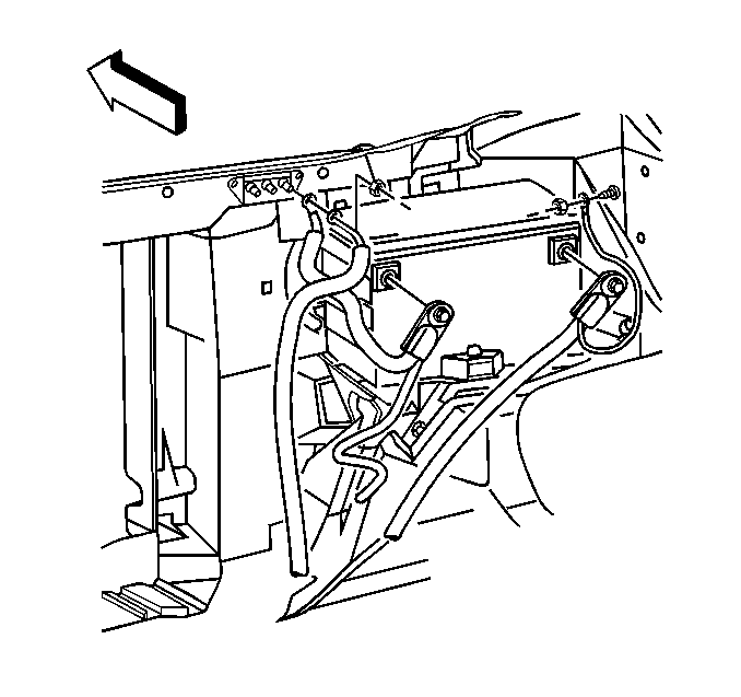
- Install the radiator support (1) to the vehicle.
- Install the ground strap bolts to the right and left fenders.
- Connect the forward lamp harness electrical connector.
- Install the radiator support (1) and bolts (3).
- If equipped, install the transmission to
auxiliary cooler lines to the cooler.
- Install the A/C condenser lines to the condenser.
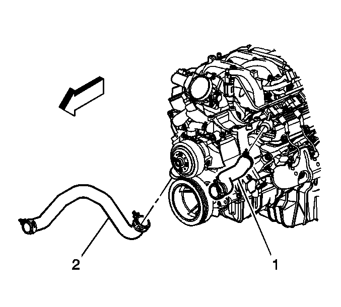
- Install the radiator outlet hose (2) to
the water pump.
- Tighten the outlet hose clamp at the water pump.
- Install the inlet hose (1) to the thermostat housing.
- Tighten the inlet hose clamp at the thermostat housing.
- Install
the intake manifold. Refer to
Intake Manifold Replacement
- Install the front bumper. Refer to
Front Bumper Replacement
in Bumpers.
- Recharge the A/C system. Refer to
Refrigerant Recovery and Recharging
in Heating, Ventilation and Air Conditioning.
- Install the radiator. Refer to
Radiator Replacement
in Engine Cooling.
- Install the grille. Refer to
Grille Replacement
in Exterior Trim.
- Install the engine cover. Refer to
Engine Cover Replacement
in Interior Trim.
- Connect the negative battery cable. Refer to
Battery Negative Cable Disconnection and Connection
in Engine Electrical.
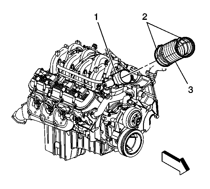
- Install the air cleaner duct (3).
- Tighten the clamp (2) at the throttle body (1).
Tighten
Tighten the air cleaner duct clamp to 4 N·m (35 lb in).
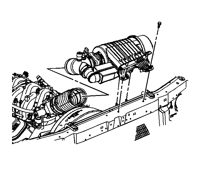
- Install the air cleaner.
- Install the air cleaner bolts.
Tighten
Tighten the air cleaner bolts to 10 N·m (89 lb in).
- Tighten the air cleaner clamp.
Tighten
Tighten the air cleaner duct clamp to 4 N·m (35 lb in).
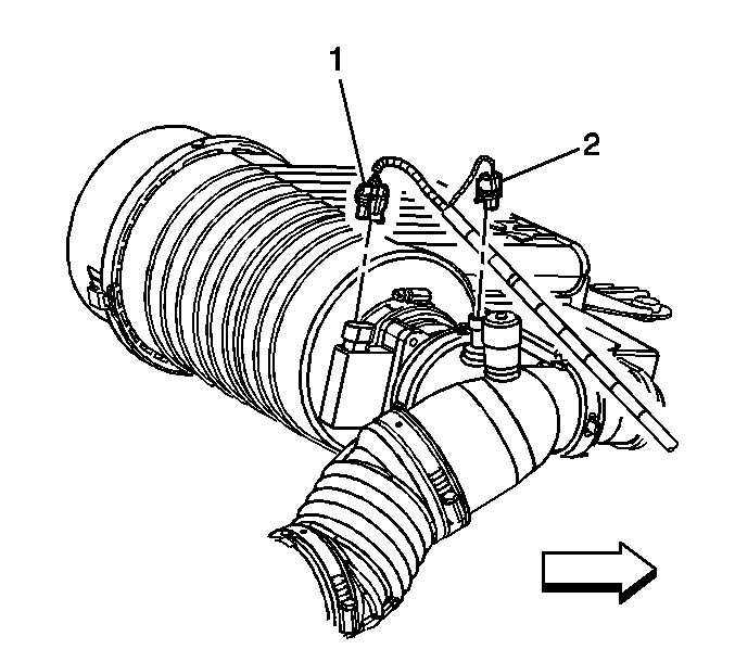
- Connect the following electrical connectors:
- Before starting a new engine or one that has been repaired complete the
following procedure.
| • | Fill the crankcase with the proper quantity and grade of oil. |
| • | Add engine oil supplement GM U.S. P/N 1052367, Canada P/N 992869,
or equivalent to the engine oil. |
| • | Remove the fuel pump fuse and disconnect the coil harness connectors,
then crank until oil pressure is present. |
| • | Crank the engine several times. Listen for any unusual noises or evidence
that any of the parts are binding. |
| • | Start the engine and listen for unusual noises. |
| • | Check the vehicle oil pressure gauge or light and confirm that the engine
has acceptable oil pressure. If necessary install an oil pressure gauge and measure
the oil pressure, |
| • | Run the engine at about 1000 RPM until the engine has reached normal
operating temperature. |
| • | Inspect for oil and or coolant leaks while the engine is running. |
| • | Stop engine and perform a final inspection for the proper engine oil
and coolant levels. |
