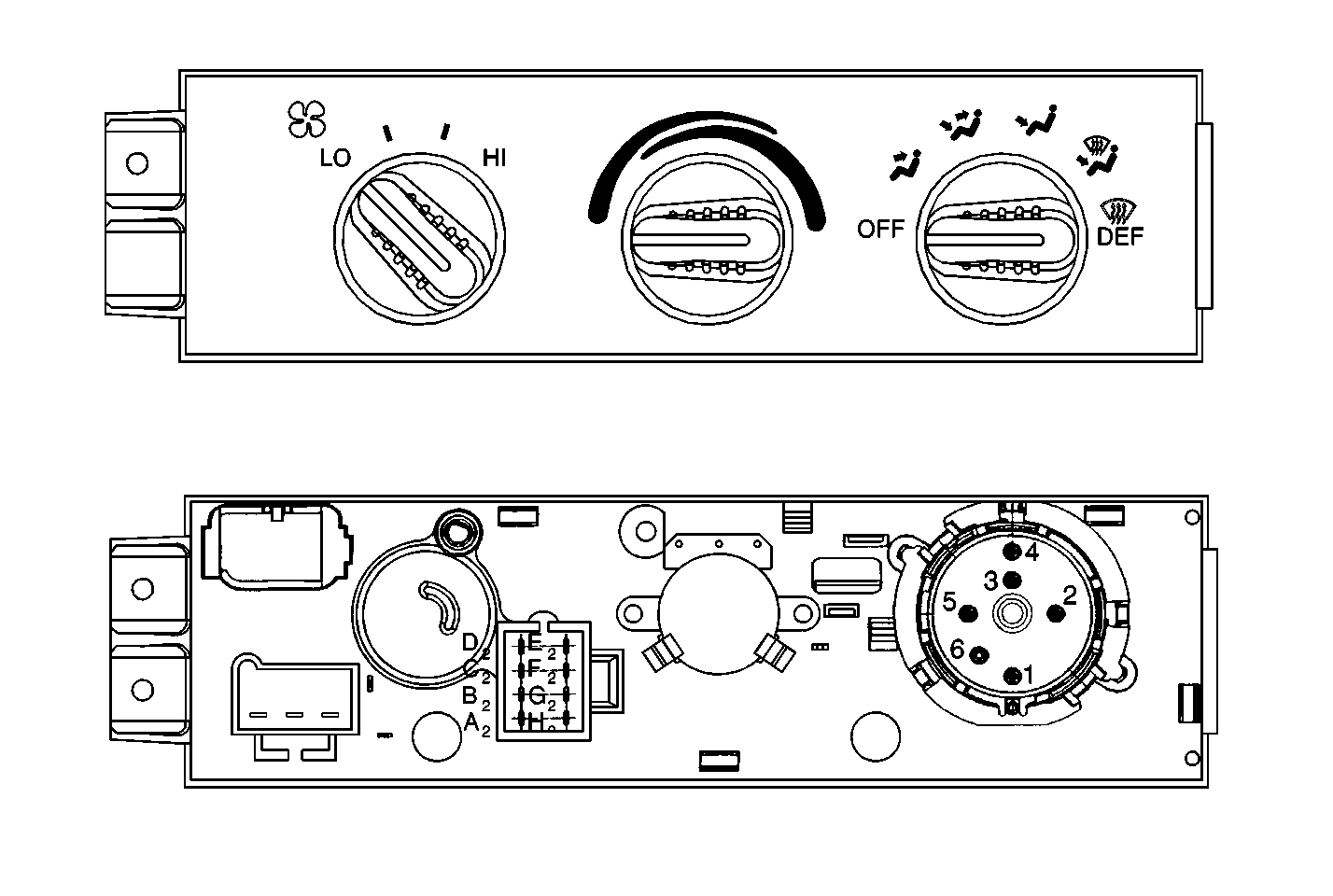
Controls

The HVAC control assembly in the instrument panel contains the following controls:
| • | A temperature knob |
| • | A mode knob |
| • | A blower motor switch |
When the headlamps are on, these controls are illuminated. Electrical voltage is provided to the HVAC control assembly through the instrument panel lighting circuit. The instrument panel dimmer switch controls the brightness of the dial illumination.
Temperature Knob
When the control assembly temperature knob is in the BLUE (cold) zone, the air delivered by the system is unheated. When the temperature knob is in the RED (hot) zone, the air passing through the heater module is heated before the air is discharged. Placing the temperature knob in the Intermediate positions results in a mixture of heated and unheated air, allowing for more moderate air temperatures.
As the temperature knob is moved away from the BLUE (cold) zone, an electronically controlled temperature valve in the heater module opens to allow an increasing amount of air to pass through the heater core. The farther the temperature knob is moved toward the RED (hot) zone, the greater the air flow through the heater core. Heating a greater portion of the total airflow in this manner results in a warmer discharge of air from the outlets.
When the temperature knob is fully in the RED (hot) zone, the temperature door blocks off the passage that allows incoming air to bypass the heater core. All of the airflow then passes through the heater core for maximum heating. This method of temperature control provides a very rapid response to any change in temperature selection once the engine is warm.
Mode Knob
The mode knob uses vacuum in order to control the doors that regulate airflow through the heater module. The primary mode knob positions are identified as follows:
| • | HTR |
| • | VENT |
| • | DEFROST |
The intermediate zones between HTR and VENT, or HTR and DEFROST are identified as BLEND. Placing the mode knob in the BLEND position sets the controls to provide a combination of the features of the 2 nearest primary modes.
Blower Motor Switch
The blower motor switch provides a choice of LOW, MEDIUM, and HIGH blower speeds. The blower motor switch receives power from the fuse block when the ignition switch is in the ON position. If the LOW speed position is selected, the circuit continues through the heater wiring harness to 2 resistors in the resistor assembly near the blower motor.
If the MEDIUM-speed position is selected, the circuit continues through the heater wiring harness to the resistor assembly, but it bypasses 1 of the 2 resistors.
If the HIGH-speed position is selected, the circuit continues through the heater wiring harness to the resistor assembly. However, both resistors are bypassed in order to provide full power to the blower motor.
From the resistor assembly, the circuit continues to the blower motor terminal where the circuit is grounded by a wire in the heater wiring harness. This wire connects to a terminal at the cowl panel sheet metal near the blower assembly in the engine compartment.
Heater Bypass Valve
The heater bypass valve is a spring-loaded valve inside of the bypass valve housing. The heater bypass valve controls the volume of coolant flow through the heater core. At low coolant flow rates, the valve remains closed, and all of the engine coolant passes through the heater core. At increased engine speeds, the valve begins to open. Upon opening, the valve limits the maximum flow of coolant through the heater core to 5-6 gallons per minute by bypassing any excess coolant. Limiting coolant flow through the heater core in this manner prevents the long-term erosion and corrosion that can result from excessive flow rates. However, an adequate amount of coolant remains available for all heat requirements.
