Refer to
DIESEL PCM, EGR, SENSORS
Refer to
Circuit Description
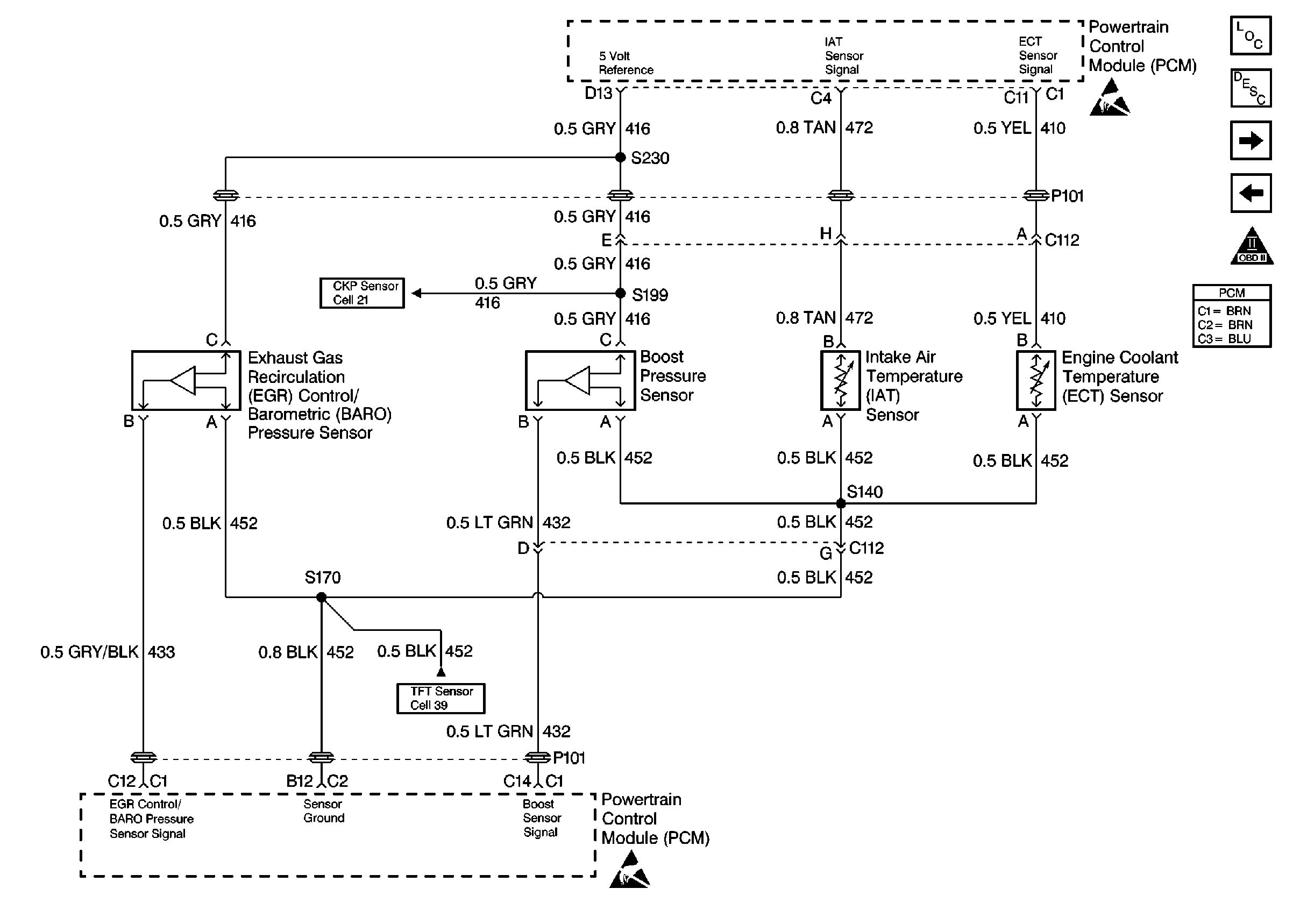
A EGR Control Pressure/Baro sensor is used to monitor the amount of vacuum in the EGR circuit. It senses the actual vacuum in the EGR vacuum line and sends a signal back to the PCM. This signal is used to control EGR duty cycle calculated by the PCM. This is a type B DTC.
Conditions for Setting the DTC
| • | Actual EGR greater than or equal to 3.96 volts (85 kPa). |
| • | Desired EGR is less than or equal to 60 kPa. |
| • | EGR vent is closed. |
| • | Conditions met for 2 seconds. |
Action Taken When the DTC Sets
PCM will shut off EGR system.
Conditions for Clearing the MIL/DTC
| • | The PCM will turn the MIL off after three consecutive trips without a fault condition. |
| • | A History DTC will clear when forty consecutive warm-up cycles that the diagnostic does not fail (coolant temperature has risen 5°C (40°F) from start up coolant temperature and engine coolant temperature exceeds 71°C (160°F) that same ignition cycle. |
| • | Use of a Scan Tool |
Diagnostic Aids
With the ignition ON and the engine stopped, the manifold pressure is equal to atmospheric pressure with the signal voltage being high. This information is used by the PCM as an indicator of vehicle altitude. If DTC P0406 is intermittent, refer to Intermittent Conditions .
To run the diagnostic test the engine must be at the operating temperature, vehicle in drive at idle for approximately 1 minute, then with the vehicle in park hold engine rpm steady between 1500 and 2100 rpm for 30 seconds. If the diagnostic test fails to run, vehicle must be driven.
The Adaptive Learn Matrix (ALM) is used to adjust the EGR vacuum control based on Mass Air Flow (MAF). The ALM may change as a result of back pressure increases over the life of the vehicle or other engine system variations. The ALM is made up of sixteen cells (numbered from zero to fifteen) in which each cell covers a range of engine speed (RPM) and load (mm3).
Test Description
Number(s) below refer to the step number(s) on the Diagnostic Table.
-
This step will check for EGR Vent Solenoid DTC.
-
This step determines if DTC P0406 is a hard failure or an intermittent condition.
-
This step simulates conditions for a DTC P0405. If the PCM recognizes the change, the PCM and the signal circuit are OK.
Step | Action | Value(s) | Yes | No |
|---|---|---|---|---|
1 |
Important: Before clearing DTCs use the scan tool Capture Info to record freeze frame and failure records for reference, as data will be lost when Clear Info function is used. Was the Powertrain On-Board Diagnostic (OBD) System Check performed? | -- | ||
Is DTC P1653 set? | -- | Go to the Applicable DTC Table | ||
Does the scan tool display EGR Control pressure/BARO sensor voltage greater than the specified value? | 4.0 V | |||
Does the scan tool display a EGR Control pressure/BARO sensor voltage less than the specified value? | 1.0 V | |||
5 | DTC is intermittent. If no additional DTCs are stored, refer to Diagnostic Aids. If additional DTCs are stored refer to those table(s) first. Are any additional DTCs stored? | -- | Go to the Applicable DTC Table | Go to Diagnostic Aids |
6 |
Is voltage greater than the specified value? | 5.2V | ||
7 | Probe the EGR Control Pressure/Baro sensor ground circuit with a test light to B+. Is the test light ON? | -- | ||
8 | Check the EGR vacuum source for a restriction. Was a problem found? | -- | ||
9 | Replace the malfunctioning EGR Control Pressure/Baro sensor. Refer to Exhaust Gas Recirculation Control Pressure Sensor Replacement . Is the action complete? | -- | -- | |
10 | Check for a short to voltage in the sensor signal circuit. Was a problem found? | -- | ||
11 |
Was a repair performed? | -- | ||
12 | Repair the open in the sensor ground circuit. Is the action complete? | -- | -- | |
13 | Repair as necessary. Is the action complete? | -- | -- | |
14 | Replace the PCM. Imp: The new PCM must be programmed. Refer to Powertrain Control Module Replacement/Programming . Is the action complete? | -- | -- | |
15 |
Important: After Repairs, the EGR ALM cells must be reset (under special functions in scan tool). Are EGR ALM cells reset? | -- | -- | |
16 |
Does the Scan Tool indicate that this diagnostic Passed? | -- | ||
17 | Using the Scan Tool, select Capture Info, Review Info. Are any DTCs displayed that have not been diagnosed? | -- | Go to the Applicable DTC Table | System OK |
