GM Service Manual Online
For 1990-2009 cars only

Removal Procedure


    Object Number: 689678  Size: SH
  1. Shift the transmission into 3rd or 4th gear.
  2. Remove the shift lever. Refer to Shift Lever Assembly Replacement .
  3. Raise and suitably support the vehicle. Refer to Lifting and Jacking the Vehicle in General Information.
  4. Important: The clutch actuator cylinder hose can remain attached to the clutch actuator. Disconnecting the hose from the clutch actuator cylinder will cause the fluid to drain from the hydraulic system.

  5. If vehicle is a 2 wheel drive (2WD), remove the rear propeller shaft. Refer to One-Piece Propeller Shaft Replacement or Two-Piece Propeller Shaft Replacement in Propeller Shaft.
  6. If equipped with 4 wheel drive (4WD), remove the transfer case. Refer to Transfer Case Assembly Replacement in Transfer Case -  NVG263-NP1 (Selectable) or Transfer Case Assembly Replacement in Transfer Case - NVG261-NP2 (Two Speed Manual).
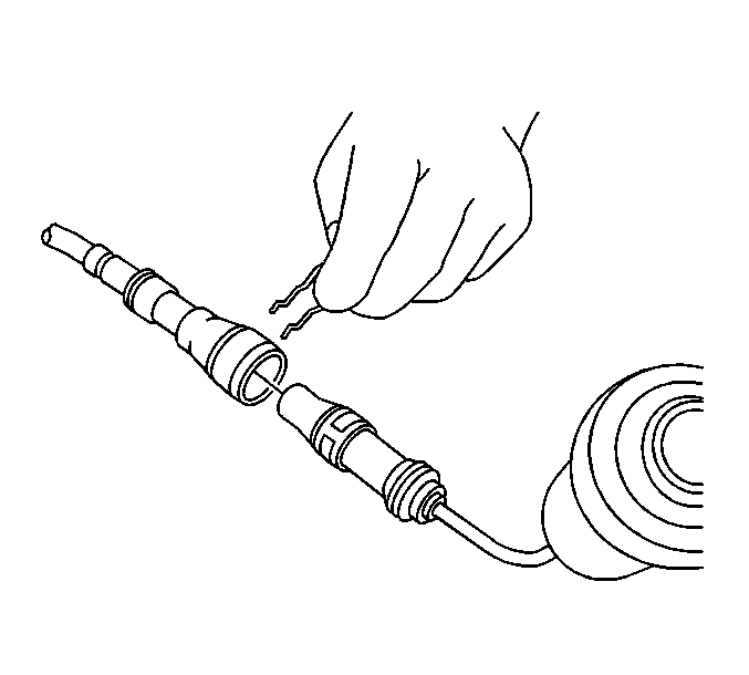
  7. Disconnect the clutch actuator cylinder hydraulic hose quick connect at the master cylinder.
  8. Disconnect the clutch actuator cylinder line retaining clips.

  9. Object Number: 776052  Size: SH
  10. If equipped with a 6.6L engine, disconnect the following electrical connectors:
  11. • Power take-off (PTO) (2), if connected
    • Backup lamp switch (3)
    • Vehicle speed sensor (VSS) (4)
  12. Remove the engine harness clips (1) from the fuel feed/return brackets.
  13. Remove the PTO connector from the fuel feed/return bracket.
  14. Reposition the harness.
  15. Remove the fuel lines from the fuel feed/return brackets.

  16. Object Number: 776054  Size: SH
  17. If equipped with a 8.1L engine, disconnect the following electrical connectors:
  18. • Power take-off (PTO) (2), if connected
    • Oxygen sensors (1, 3)
    • Backup lamp switch (4)
    • VSS (5)
  19. Remove the engine harness clips (6) from the fuel feed/return brackets.
  20. Remove the PTO connector from the fuel feed/return bracket.
  21. Remove the oxygen sensors connectors (1, 3) from the fuel feed/return hose clip and transmission bracket.
  22. Reposition the harness.
  23. Remove the fuel lines from the fuel feed/return brackets.

  24. Object Number: 775346  Size: SH
  25. If equipped with 4WD, remove the vent hose clip from the bracket.
  26. Remove the vent hose clip nut and clip.

  27. Object Number: 776223  Size: SH
  28. If equipped with 4WD, remove the vent hose clip (1) from the fuel feed/return bracket.
  29. Remove the starter. Refer to Starter Motor Replacement in Engine Electrical.

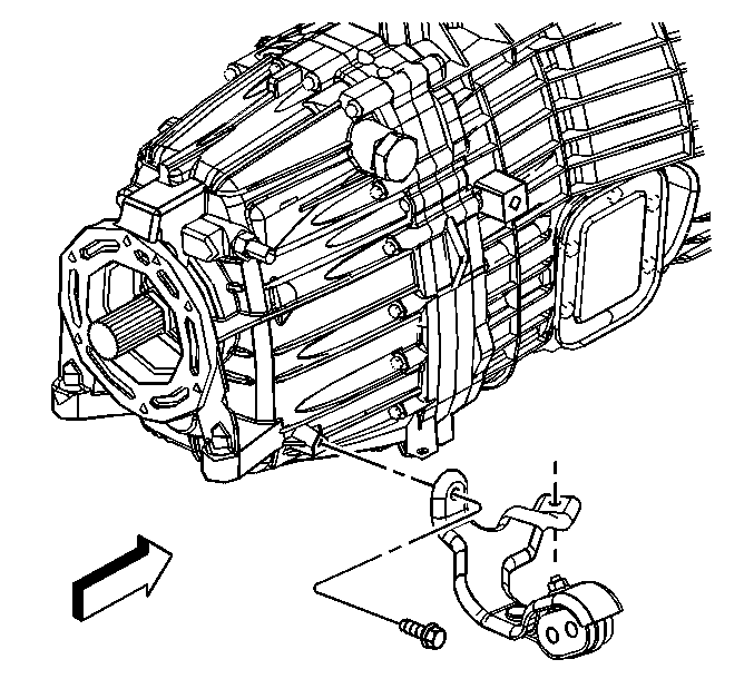
  30. Object Number: 694241  Size: SH
  31. Remove the exhaust pipe hanger bracket bolts and bracket.
  32. Support the transmission with a suitable transmission jack.
  33. Remove the transmission support. Refer to Transmission Support Replacement in Frame and Underbody.

  34. Object Number: 776274  Size: SH
  35. If equipped with a 6.6L engine, remove the transmission bolts/studs.
  36. Pull the transmission straight back on the clutch hub splines. Do not let the transmission hang from the clutch assembly.
  37. Remove the transmission from the vehicle with the clutch hydraulic hose attached to the clutch actuator.
  38. Remove the insulator from the top of the transmission.

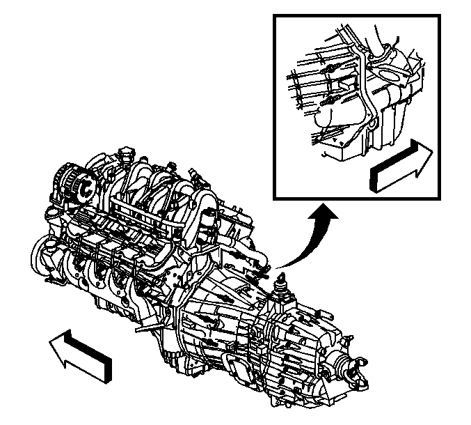
  39. Object Number: 776275  Size: SH
  40. If equipped with a 8.1L engine, remove the transmission studs.
  41. Pull the transmission straight back on the clutch hub splines. Do not let the transmission hang from the clutch assembly.
  42. Remove the transmission from the vehicle with the clutch hydraulic hose attached to the clutch actuator.
  43. Remove the insulator from the top of the transmission.

Installation Procedure


    Object Number: 776275  Size: SH
  1. Install the insulator to the top of the transmission.
  2. Notice: Connect the clutch actuator cylinder hose quick connect to the master cylinder before the transmission is fully installed. Failure to connect the hose could cause damage to the clutch pressure plate.

  3. Slowly feed the clutch hydraulic hose towards the clutch master cylinder and connect the clutch actuator cylinder hydraulic hose quick connect to the master cylinder.
  4. Rotate the transmission clockwise onto the clutch hub splines.
  5. Position the transmission to the engine. Do not use the transmission bolts to draw up the transmission.
  6. Notice: Refer to Fastener Notice in the Preface section.

  7. If equipped with a 8.1L engine, install the transmission studs.
  8. Tighten
    Tighten the studs to 50 N·m (37 lb ft).
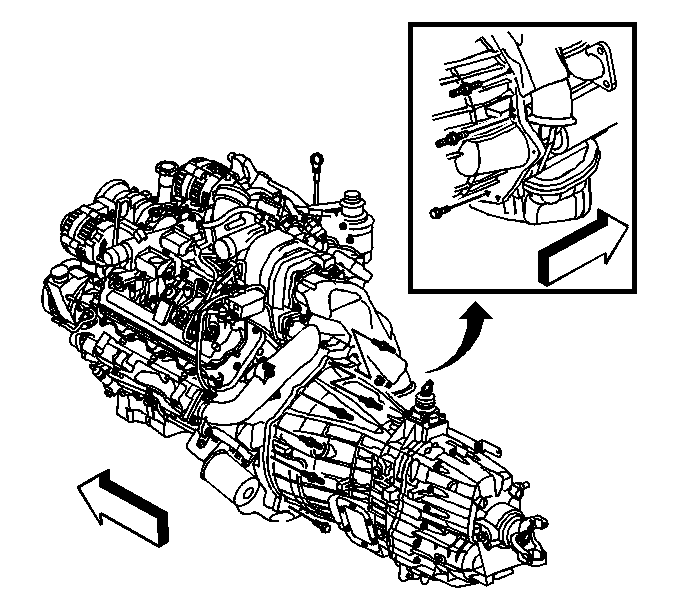

    Object Number: 776274  Size: SH
  9. Install the insulator to the top of the transmission.
  10. Notice: Connect the clutch actuator cylinder hose quick connect to the master cylinder before the transmission is fully installed. Failure to connect the hose could cause damage to the clutch pressure plate.

  11. Slowly feed the clutch hydraulic hose towards the clutch master cylinder and connect the clutch actuator cylinder hydraulic hose quick connect to the master cylinder.
  12. Rotate the transmission clockwise onto the clutch hub splines.
  13. Position the transmission to the engine. Do not use the transmission bolts to draw up the transmission.
  14. If equipped with a 6.6L engine, install the transmission bolts/studs.
  15. Tighten
    Tighten the bolts/studs to 50 N·m (37 lb ft).

  16. Install the transmission support. Refer to Transmission Support Replacement in Frame and Underbody.
  17. Remove the transmission jack.

  18. Object Number: 694241  Size: SH
  19. Install the exhaust pipe hanger bracket and bolts.
  20. Tighten
    Tighten the bolts to 12 N·m (106 lb in).

  21. Install the starter. Refer to Starter Motor Replacement in Engine Electrical.
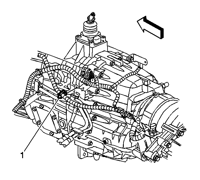
  22. Object Number: 776223  Size: SH
  23. If equipped with 4WD, install the vent hose clip (1) to the fuel feed/return bracket.
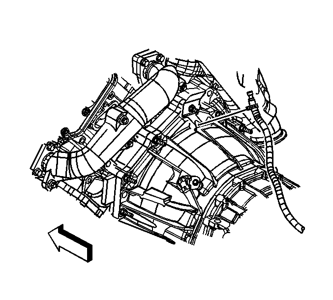
  24. Object Number: 775346  Size: SH
  25. Install the vent hose clip and nut.
  26. Tighten
    Tighten the nut to 25 N·m (18 lb ft).

  27. If equipped with 4WD, install the vent hose clip to the bracket.
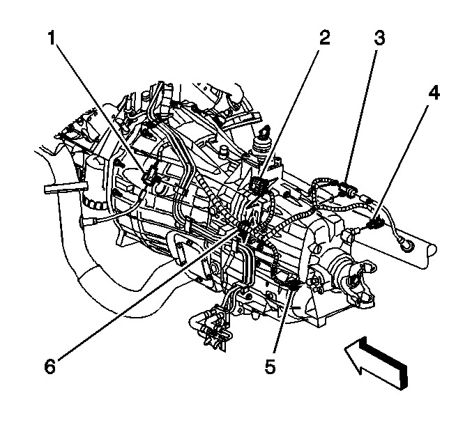
  28. Object Number: 776054  Size: SH
  29. Install the fuel lines to the fuel feed/return brackets.
  30. Position the harness.
  31. Install the oxygen sensors connectors (1, 3) to the fuel feed/return hose clip and transmission bracket.
  32. Install the PTO connector to the fuel feed/return bracket.
  33. Install the engine harness clips (6) to the fuel feed/return brackets.
  34. If equipped with a 8.1L engine, connect the following electrical connectors:
  35. • PTO (2), if connected
    • Oxygen sensors (1, 3)
    • Backup lamp switch (4)
    • VSS (5)

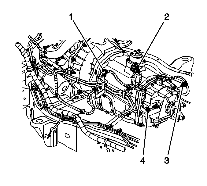
    Object Number: 776052  Size: SH
  36. Install the fuel lines to the fuel feed/return brackets.
  37. Position the harness.
  38. Install the PTO connector to the fuel feed/return bracket.
  39. Install the engine harness clips (1) to the fuel feed/return brackets.
  40. If equipped with a 6.6L engine, connect the following electrical connectors:
  41. • PTO (2), if connected
    • Backup lamp switch (3)
    • VSS (4)

    Object Number: 689678  Size: SH
  42. Connect the clutch actuator cylinder line retaining clips.
  43. Important: Improper connection may cause the quick connect from locking properly. Before pushing in the clutch pedal fully, check with light pressure. If pedal is hard recheck the connection.

  44. If equipped with 4WD, install the transfer case. Refer to Transfer Case Assembly Replacement in Transfer Case - NVG263-NP1 (Selectable) or Transfer Case Assembly Replacement in Transfer Case - NVG261-NP2 (Two Speed Manual).
  45. If vehicle is a 2WD, install the rear propeller shaft. Refer to One-Piece Propeller Shaft Replacement or Two-Piece Propeller Shaft Replacement in Propeller Shaft.
  46. Lower the vehicle.
  47. Install the shift lever. Refer to Shift Lever Assembly Replacement .
  48. Fill the transmission with fluid.
  49. Bleed the clutch hydraulic system, if necessary. Refer to Hydraulic Clutch Bleeding in Clutch.