Removal Procedure
Important:
• Ensure that the control lever is positioned into the mechanical third
or fourth gear prior to removal of the shift lever assembly from the transmission.
The transmission must remain in this state when the shift lever assembly is removed. • When removing the shift lever assembly from the transmission, use the
exposed bolts on the base of the shift lever assembly.
- Remove the control lever and boot. Refer to Control Lever and/or Boot Replacement .
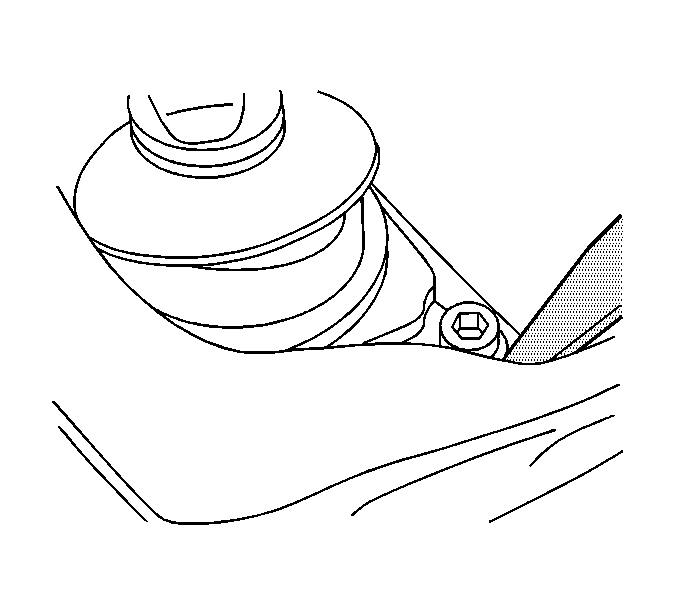
- With a flat-bladed tool, pull back the insulator between the body and transmission to access the shift tower bolts.
- Remove the boot.
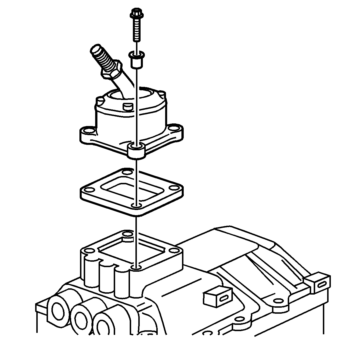
- Remove the shift lever bolts.
- Remove the shift lever and seal.
- Remove the shift lever insulator.
Installation Procedure
- Install a NEW shift lever insulator, if required.
- Apply gasket maker GM P/N 12378517 or equivalent to the surface of the control lever assembly.
- Push the shift lever assembly back through the insulator, position and turn the shift lever assembly back into place.
- With a flat tool pull back the insulator between the body and transmission to install the shift lever assembly bolts.
- Install the slift lever assembly bolts.
- Install the control lever and boot. Refer to Control Lever and/or Boot Replacement .
Notice: Use the correct fastener in the correct location. Replacement fasteners must be the correct part number for that application. Fasteners requiring replacement or fasteners requiring the use of thread locking compound or sealant are identified in the service procedure. Do not use paints, lubricants, or corrosion inhibitors on fasteners or fastener joint surfaces unless specified. These coatings affect fastener torque and joint clamping force and may damage the fastener. Use the correct tightening sequence and specifications when installing fasteners in order to avoid damage to parts and systems.
Tighten
Tighten the bolts to 23 N·m (17 lb ft).
