GM Service Manual Online
For 1990-2009 cars only
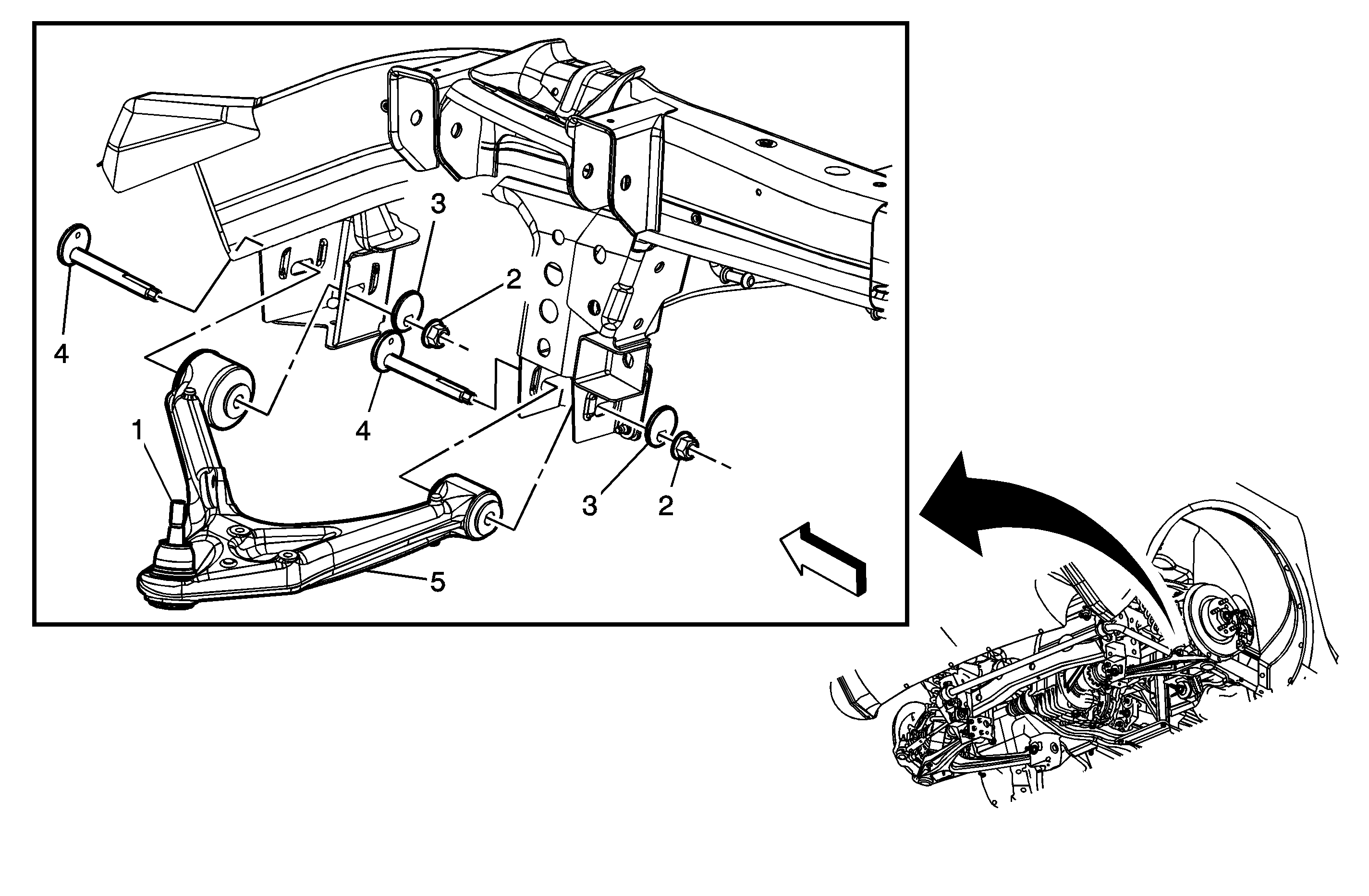
Object Number: 1589188  Size: MF

Callout

Component Name

Notice: The ball stud must not rotate during disassembly or reassembly. Hand tools must be used to keep the ball stud from rotating. If air tools are used and the stud is allowed to rotate, damage to the ball stud and/or stud mounting hole may occur.

Preliminary Procedures

  1. Disconnect the stabilizer link from the lower control arm. Refer to Stabilizer Shaft Link Replacement .
  2. Disconnect the shock module from the lower control arm. Refer to Shock Absorber and Spring Assembly Replacement .
  3. Separate the rear adjustment link from the suspension knuckle. DO NOT loosen the adjustment jamb nut. Refer to Adjust Link Replacement .

1

Lower Control Arm Ball Joint

Notice: Refer to Fastener Notice in the Preface section.

Tip

    • Rotate the forward edge of the knuckle outboard to gain access for the J-42188-B Ball Joint Separator.
    • Loosen but DO NOT remove the nut until the ball stud has been separated from the knuckle.
    • Using the J-42188-B , separate the ball stud from the knuckle.
    • Adjust the rear caster and camber. Refer to Rear Caster and Camber Adjustment .

Tighten
40 N·m (30 lb ft) ± 135 degrees.

2

Lower Control Arm Nut (Qty: 2)

Tip
Prior to removing the lower control arm nuts, index the adjusting cams for ease during installation.

Tighten
165 N·m (122 lb ft)

3

Adjusting Cam

4

Lower Control Arm to Frame Bolt (Qty: 2)

5

Lower Control Arm Assembly

Tip
Verify the 4-wheel alignment. Refer to Wheel Alignment Measurement .