For 1990-2009 cars only
Removal Procedure
- Remove the access panel.
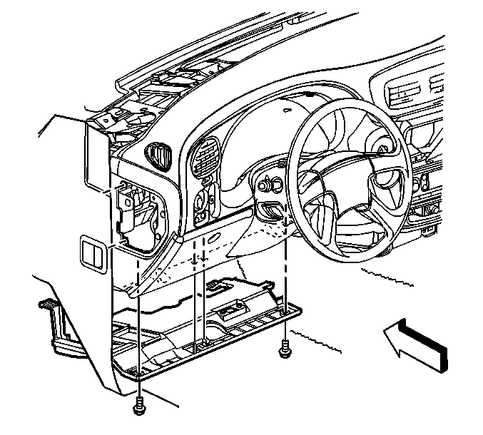
- Remove the left side closeout/insulator panel. Refer to Instrument Panel Insulator Panel Replacement - Left Side.
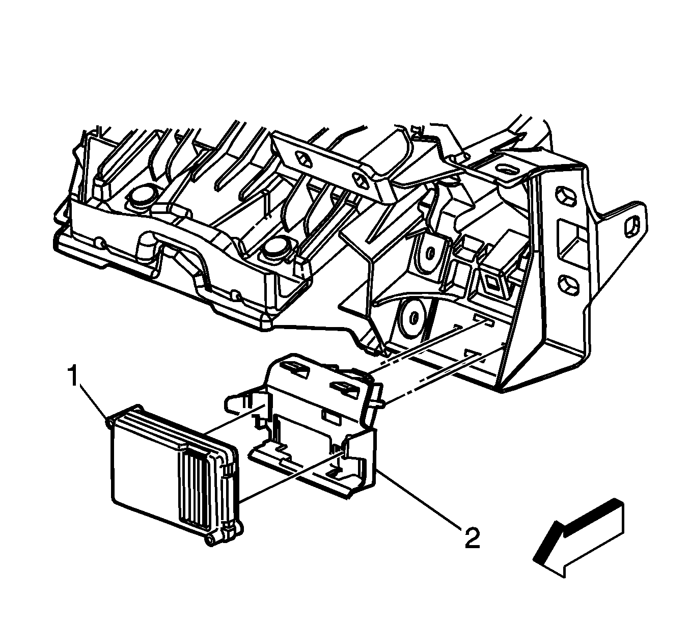
- Remove the transfer case control module (1) and mounting bracket from the instrument panel mag beam.
- Disconnect the three electrical connectors from the transfer case control module.
- Remove the transfer case control module from the mounting bracket.
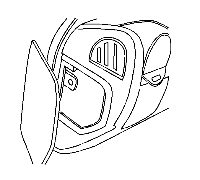
Important: The access panel is removed in order to visually see the electrical connectors and the location of the transfer case control module. It will also be easier to see the mounting and alignment slots for the transfer case control module mounting bracket.
Installation Procedure
- Install the transfer case control module (1) to the mounting bracket.
- Connect the three electrical connectors to the transfer case control module.
- Install the transfer case control module and mounting bracket to the instrument panel mag beam.
- Install the left side closeout/insulator panel. Refer to Instrument Panel Insulator Panel Replacement - Left Side.
- Install the access panel.
- Program the transfer case shift control module. Refer to Transfer Case Shift Control Module Reprogramming .
