Circuit Description
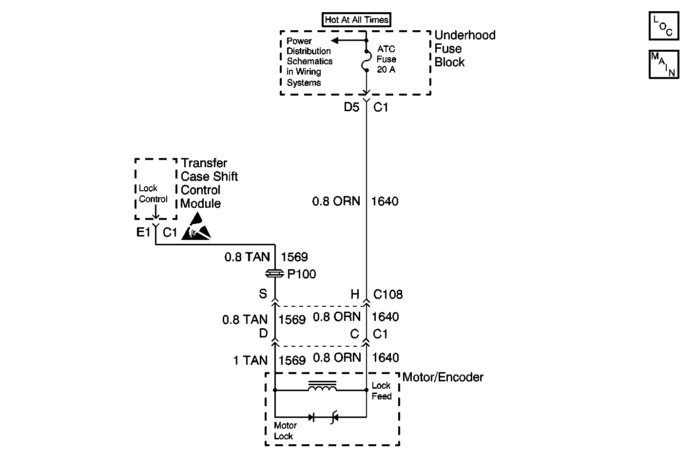
The transfer case shift control module controls the Transfer Case Lock Solenoid. The lock is energized (locking action released, by grounding the Lock Control Circuit) during gear shifts and in AUTO 4WD mode of operation. When power or ground is removed from the lock solenoid (locking action applied, releasing the ground on the Lock Control Circuit), the Transfer Case Motor is prevented from moving. In this manner the system is capable of providing a 4H and 4L lock-up without the need of additional vehicle power to hold the Transfer Case in these positions.
This DTC detects a shorted lock solenoid coil, or the Lock Control Circuit shorted to 12 V.
Conditions for Setting the DTC
Transfer Case Lock output reads back as a high voltage when a low voltage is expected.
Action Taken When the DTC Sets
| • | The system will try to turn the lock solenoid on, grounding the Lock Control Circuit; if unable to energize the solenoid, the system will not attempt to energize the solenoid again during that ignition cycle. |
| • | All shifting will be disabled. |
| • | The SERVICE indicator (4WD/AWD) lamp will be latched on for the remainder of current ignition cycle. |
Conditions for Clearing the DTC
| • | The transfer case shift control module will clear the DTC if the condition for setting the DTC no longer exists. |
| • | A history DTC will clear after 100 consecutive ignition cycles without a fault present. |
| • | History DTCs can be cleared using a scan tool. |
Test Description
The number(s) below refer to the step number(s) on the diagnostic table.
-
Measures the resistance across the encoder motor brake.
-
Tests the Transfer Case Lock circuit for a short to voltage.
Step | Action | Value(s) | Yes | No |
|---|---|---|---|---|
1 | Was the Transfer Case Diagnostic System Check performed? | -- | Go to Step 2 | Go to Diagnostic System Check |
Is the resistance reading within the specified values? | 18-25 ohms | Go to Step 3 | Go to Step 5 | |
Does the test lamp illuminate? | -- | Go to Step 4 | Go to Step 6 | |
4 | Repair the Transfer Case Lock circuit for a short to voltage. Refer to Wiring Repairs in Wiring Systems. Is the repair complete? | -- | Go to Step 7 | -- |
5 | Replace the encoder motor. Refer to Motor/Encoder Replacement . Is the repair complete? | -- | Go to Step 7 | -- |
6 | Replace the transfer case shift control module. Refer to Transfer Case Shift Control Module Replacement . Is the repair complete? | -- | Go to Step 7 | -- |
7 |
Does the DTC reset? | -- | Go to Step 2 | System OK |
