Tools Required
J 43631 Ball Joint Separating Tool
Removal Procedure
- Siphon brake fluid from the master cylinder.
- Raise and support the vehicle. Refer to Lifting and Jacking the Vehicle in General Information.
- Remove the tire and wheel assembly from the vehicle. Refer to Tire and Wheel Removal and Installation in Tires and Wheels.
- Compress the brake caliper piston with a C-clamp.
- Remove the 2 brake caliper mounting bolts.
- Remove the caliper from the rotor. Suspend the caliper assembly with wire in order to prevent damage to the brake hose.
- Remove the brake rotor. Refer to Brake Rotor Replacement in Disc Brakes.
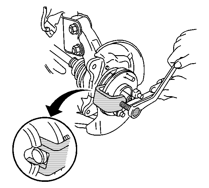
- Install 2 wheel nuts onto 2 wheel studs.
- Use a pry bar on the 2 nuts in order to prevent the hub from turning.
- Use the J 43631 in order to remove the wheel stud from the hub.
- Remove the wheel nut from the stud.
CAUTION:: If one stud is damaged, replace all the studs. A loose-running wheel may cause only one stud to break, but the other studs could have internal fatigue. Replacing only the broken stud and remounting the wheel may cause further damage and personal injury. If the stud holes in the wheels have become enlarged or distorted, replace the wheel.
Notice: Do not allow the brake components to hang from the flexible brake hoses. Damage to the brake hoses could result.
Installation Procedure
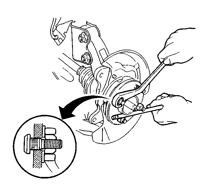
- Install the wheel stud into the wheel stud hole.
- Install a washer and the wheel nut on the wheel stud.
- Install 2 wheel nuts onto 2 wheel studs.
- Use a pry bar on the 2 nuts in order to prevent the hub from turning.
- Pull the wheel stud with the wheel nut.
- If necessary, tighten the wheel nut in order to seat the wheel stud.
- Remove the 3 wheel nuts and the washer.
- Install the brake rotor. Refer to Brake Rotor Replacement in Disc Brakes.
- Install the brake caliper assembly to the steering knuckle. Secure the brake caliper assembly with two brake caliper mounting bolts.
- Install the tire and wheel assembly to the vehicle. Refer to Tire and Wheel Removal and Installation in Tires and Wheels.
- Lower the vehicle.
- Fill the brake master cylinder reservoir. Refer to Master Cylinder Reservoir Filling in Hydraulic Brakes.
Notice: Use the correct fastener in the correct location. Replacement fasteners must be the correct part number for that application. Fasteners requiring replacement or fasteners requiring the use of thread locking compound or sealant are identified in the service procedure. Do not use paints, lubricants, or corrosion inhibitors on fasteners or fastener joint surfaces unless specified. These coatings affect fastener torque and joint clamping force and may damage the fastener. Use the correct tightening sequence and specifications when installing fasteners in order to avoid damage to parts and systems.
Tighten
Tighten the bolts to 88 N·m (65 lb ft).
