Front Wheel Bearings Looseness Diagnosis
The following procedure describes how to inspect the front wheel bearings for excessive looseness. In order to inspect the wheel bearings for excessive runout, refer to Hub/Axle Flange and Wheel Stud Runout Inspection in Vibration Diagnosis and Correction.
Tools Required
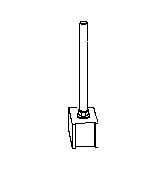
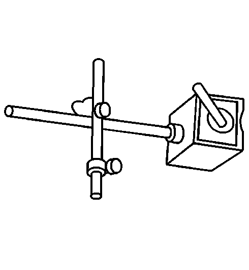
| • | J 8001 Dial Indicator Set |
| • | J 26900-13 Magnetic Indicator Base |
- Raise and support the vehicle. Refer to Lifting and Jacking the Vehicle in General Information.
- Remove the front tire and wheel assembly from the vehicle. Refer to Tire and Wheel Removal and Installation in Tires and Wheels.
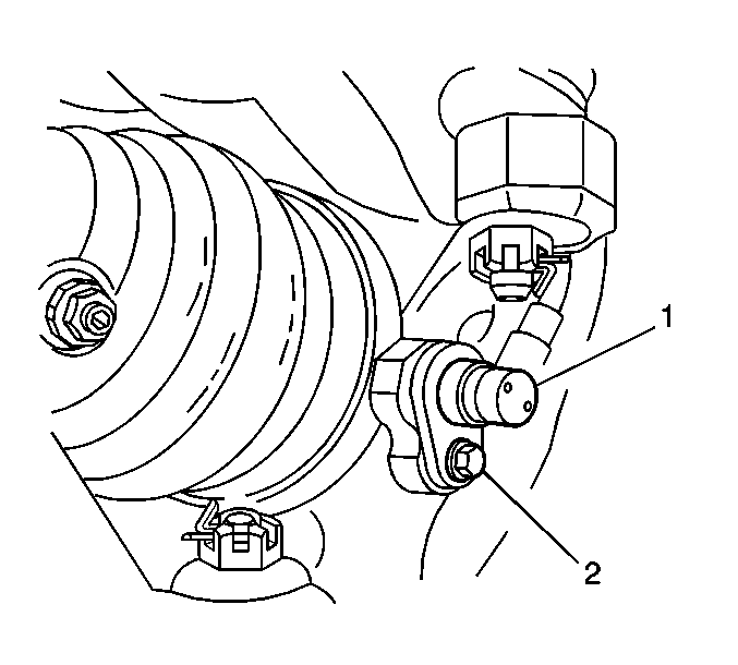
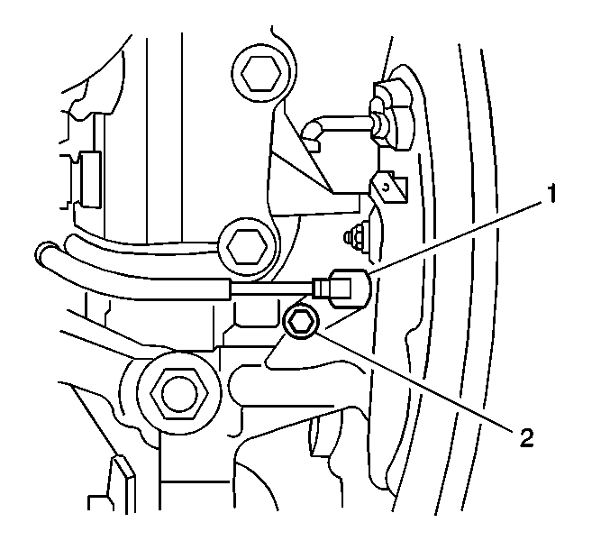
- If the vehicle has ABS, remove the bolt (2) and the front wheel speed sensor (1) from the steering knuckle. Position the sensor to the side.
- Remove the front brake hose bolt and the hose from the strut. Position the hose and the bolt to the side.
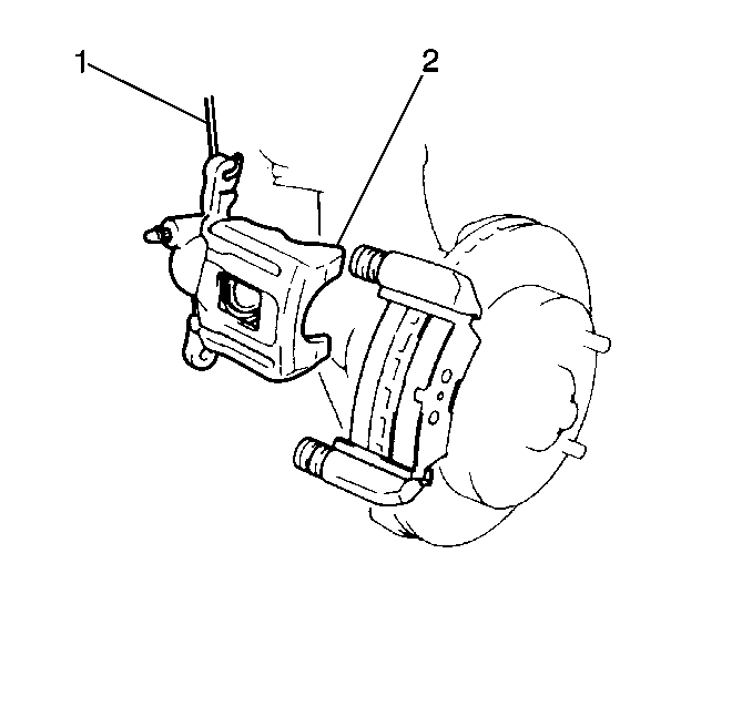
- Remove the front brake caliper housing and the brake caliper bracket. Suspend the caliper housing with wire in order to prevent damage to the brake hose. Refer to Brake Caliper Bracket Replacement in Disc Brakes.
- Remove the brake rotor. Refer to Brake Rotor Replacement in Disc Brakes.
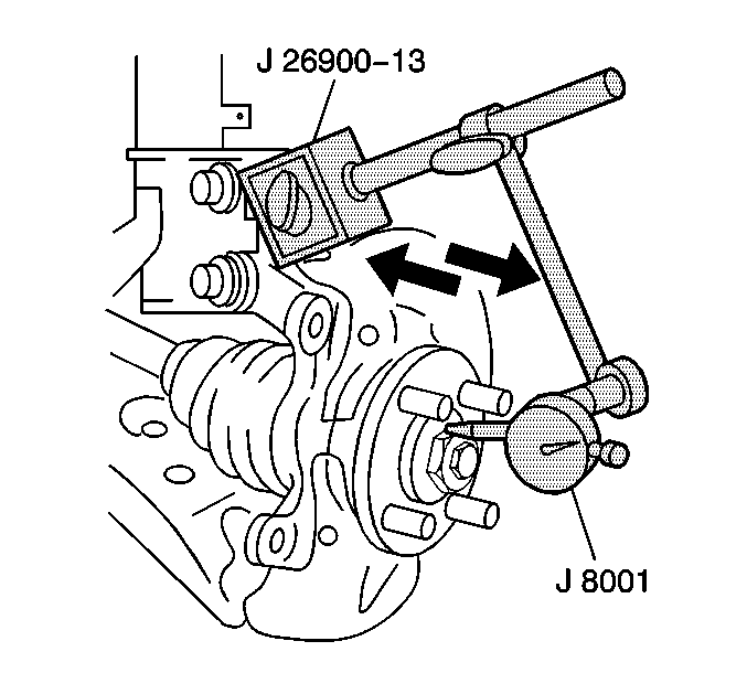
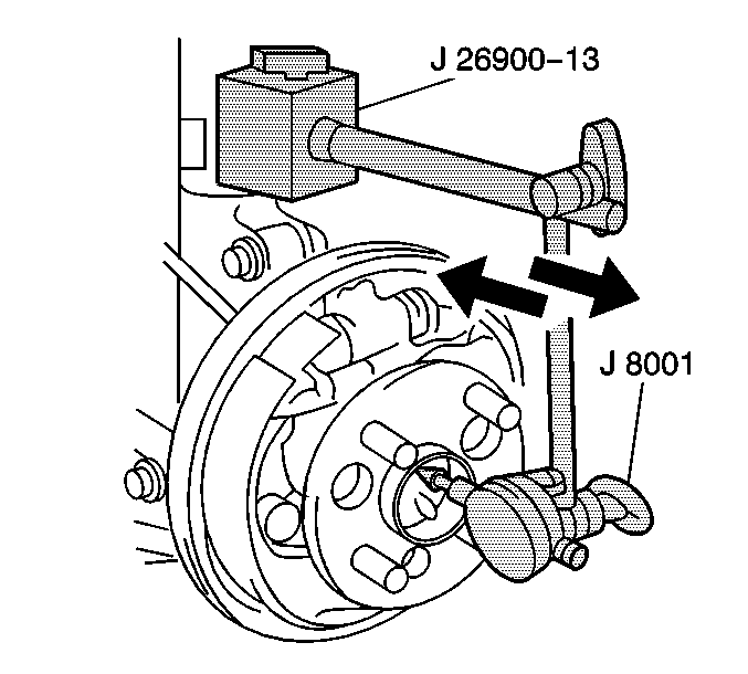
- Place the J 8001 with the J 26900-13 near the center of the axle hub.
- Push and pull the hub flange.
- Use the J 8001 in order to measure the looseness of the wheel bearings.
- Replace the front wheel bearings if the measurement exceeds the specification. Refer to Front Wheel Hub, Bearing, and Seal Replacement in Front Suspension.
- Install the brake rotor. Refer to Brake Rotor Replacement in Disc Brakes.
- Install the brake caliper bracket. Refer to Brake Caliper Bracket Replacement in Disc Brakes.
- Install the brake pads, the insulators, the retainers, and the wear indicator. Refer to Brake Pads Replacement in Disc Brakes.
- Install the brake caliper. Refer to Brake Caliper Replacement in Disc Brakes.
- If the vehicle has ABS, install the front wheel speed sensor (1). Secure the sensor to the knuckle with the bolt (2).
- Install the tire and wheel assembly. Refer to Tire and Wheel Removal and Installation in Tires and Wheels.
- Lower the vehicle.
Notice: Do not allow the brake components to hang from the flexible brake hoses. Damage to the brake hoses could result.
Notice: Use care in order to not damage the boot and the inner oil seal.
Notice: On vehicles equipped with ABS, use care to not damage the speed sensor rotor of the drive axle.
Specification
The maximum wheel bearings looseness is 0.05 mm (0.0020 in).
Notice: Use the correct fastener in the correct location. Replacement fasteners must be the correct part number for that application. Fasteners requiring replacement or fasteners requiring the use of thread locking compound or sealant are identified in the service procedure. Do not use paints, lubricants, or corrosion inhibitors on fasteners or fastener joint surfaces unless specified. These coatings affect fastener torque and joint clamping force and may damage the fastener. Use the correct tightening sequence and specifications when installing fasteners in order to avoid damage to parts and systems.
Tighten
Tighten the bolt to 7.8 N·m (69 lb in).
Rear Wheel Bearings Looseness Diagnosis
The following procedure describes how to inspect the rear wheel bearings for excessive looseness. In order to inspect the wheel bearings for excessive runout, refer to Hub/Axle Flange and Wheel Stud Runout Inspection in Vibration Diagnosis and Correction.
Tools Required
| • | J 8001 Dial Indicator Set |
| • | J 26900-13 Magnetic Indicator Base |
- Raise and support the vehicle. Refer to Lifting and Jacking the Vehicle in General Information.
- Remove the tire and wheel assembly. Refer to Tire and Wheel Removal and Installation in Tires and Wheels.
- If the vehicle has ABS, remove the bolt (2) and the wheel speed sensor (1) from the knuckle.
- Remove the brake drum. Refer to Brake Drum Replacement in Drum Brakes.
- Place the J 8001 with the J 26900-13 near the center of the axle hub.
- Push and pull the hub flange.
- Use the J 8001 in order to measure the looseness of the wheel bearings.
- Replace the rear wheel bearings if the measurement exceeds the specification. Refer to Front Wheel Hub, Bearing, and Seal Replacement in Rear Suspension.
- Install the brake drum. Refer to Brake Drum Replacement in Drum Brakes.
- If the vehicle has ABS, install the rear wheel speed sensor (1). Secure the sensor to the knuckle with the bolt (2).
- Install the tire and wheel assembly. Refer to Tire and Wheel Removal and Installation in Tires and Wheels.
- Lower the vehicle.
Specification
The maximum wheel bearings looseness is 0.05 mm (0.0020 in).
Notice: Use the correct fastener in the correct location. Replacement fasteners must be the correct part number for that application. Fasteners requiring replacement or fasteners requiring the use of thread locking compound or sealant are identified in the service procedure. Do not use paints, lubricants, or corrosion inhibitors on fasteners or fastener joint surfaces unless specified. These coatings affect fastener torque and joint clamping force and may damage the fastener. Use the correct tightening sequence and specifications when installing fasteners in order to avoid damage to parts and systems.
Tighten
Tighten the bolt to 7.8 N·m (69 lb in).
