For 1990-2009 cars only
Removal Procedure
- Disconnect the negative battery cable.
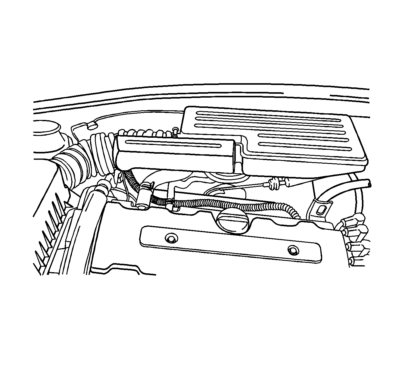
- Disconnect the intake air temperature (IAT) sensor connector.
- Disconnect the air cleaner outlet hose from the throttle body.
- Disconnect the breather tube from the camshaft cover.
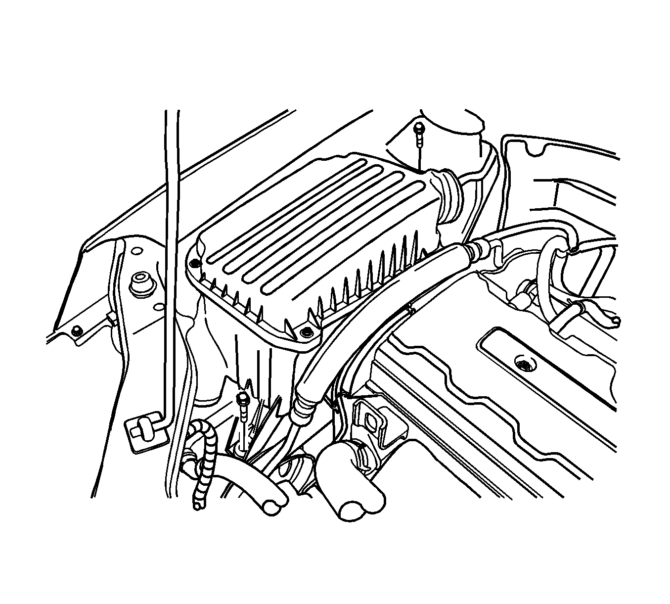
- Remove the air cleaner housing bolts.
- Remove the air cleaner housing.
- Remove the right front wheel. Refer to Tire and Wheel Removal and Installation in Tires and Wheels.
- Remove the right front wheel well splash shield. Refer to Wheelhouse Splash Shield Replacement in Body Front End.
- Remove the serpentine accessory drive belt. Refer to Power Steering Pump Belt Replacement in Power Steering System.
- Remove the crankshaft pulley bolts.
- Remove the crankshaft pulley.
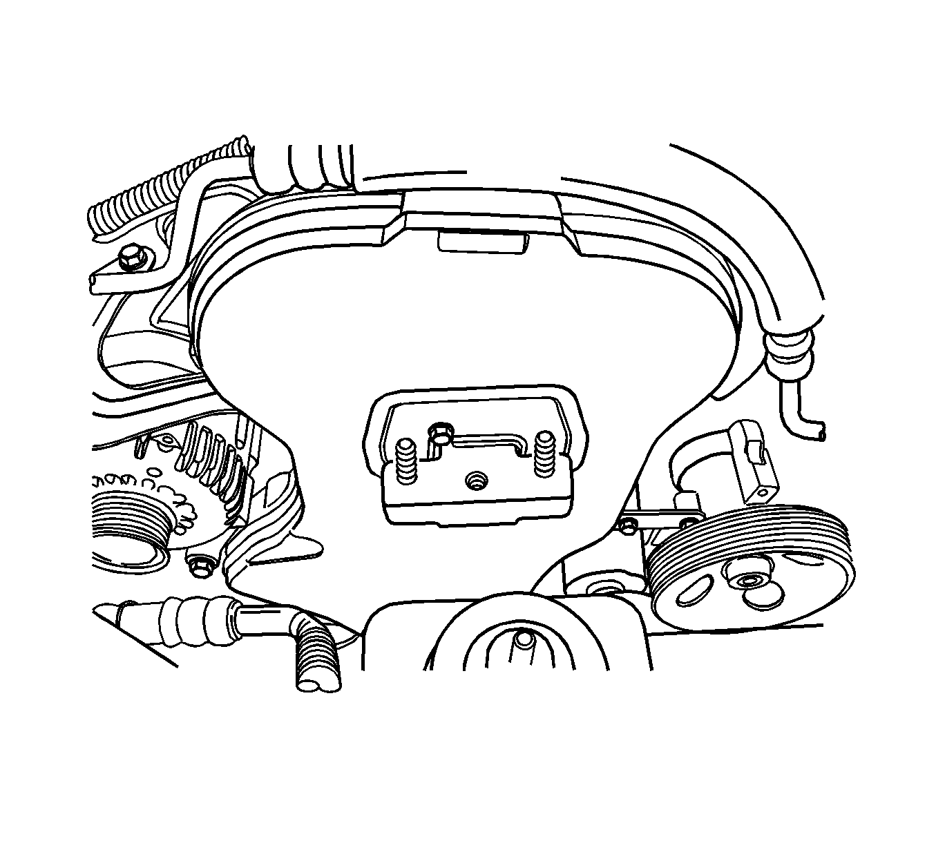
- Remove the right engine mount bracket. Refer to Engine Mount Replacement .
- Remove the front timing belt cover bolts.
- Remove the front timing belt cover.
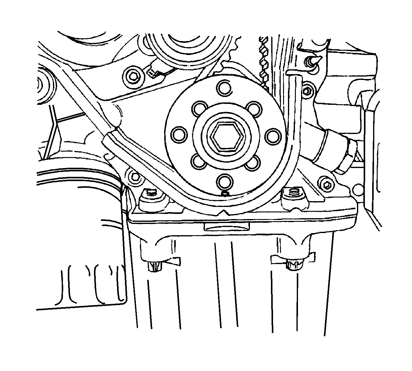
- Using the crankshaft gear bolt, rotate the crankshaft clockwise until the timing mark on the crankshaft gear is aligned with the notch at the bottom of the rear timing belt cover.
- Align the camshaft gear notch (1, 2) with the notch on the camshaft cover.
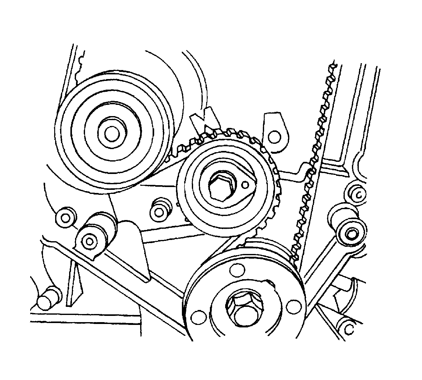
- Loosen the automatic tensioner bolt. Turn the hex-key tab to relieve belt tension.
- Remove the timing belt.
Caution: Refer to Battery Disconnect Caution in the Preface section.


Important: The camshaft gears must align with the notch on the camshaft cover or damage to the engine could result.
Important: Use the intake gear mark for the intake camshaft gear and the exhaust gear mark for the exhaust camshaft gear since both gears are interchangeable.

Installation Procedure
- Align the timing mark on the crankshaft gear with the notch on the bottom of the rear timing belt cover.
- Align the timing marks on the camshaft gears, using the intake gear mark (1) for the intake gear and the exhaust gear mark (2) for the exhaust gear.
- Install the timing belt.
- Turn the hex-key tab in a clockwise direction to tension the belt. Turn until the pointer aligns with the notch.
- Install the automatic tensioner bolt.
- Rotate the crankshaft 2 full turns clockwise using the crankshaft pulley bolt.
- Recheck the automatic tensioner pointer.
- Install the front timing belt cover.
- Install the front timing belt cover bolts.
- Install the right engine mount bracket. Refer to Engine Mount Replacement .
- Install the crankshaft pulley.
- Install the crankshaft pulley bolts.
- Install the serpentine accessory drive belt. Refer to Power Steering Pump Belt Replacement in Power Steering System.
- Install the right front wheel well splash shield. Refer to Wheelhouse Splash Shield Replacement in Body Front End.
- Install the right front wheel. Refer to Tire and Wheel Removal and Installation in Tires and Wheels.
- Install the air cleaner housing.
- Install the air cleaner housing bolts.
- Connect the air cleaner outlet hose to the throttle body.
- Connect the breather tube to the camshaft cover.
- Connect the IAT sensor connector.
- Connect the negative battery cable.


Notice: Refer to Fastener Notice in the Preface section.
Tighten
Tighten the automatic tensioner bolt to 25 N·m (18 lb ft).

Tighten
Tighten the front timing belt cover bolts to 6 N·m (53 lb in).

Tighten
Tighten the crankshaft pulley bolts to 20 N·m (15 lb ft).
Tighten
Tighten the air cleaner housing bolts to 10 N·m (89 lb in).

