For 1990-2009 cars only
Removal Procedure
- Remove the intake manifold cover. Refer to Intake Manifold Cover Replacement .
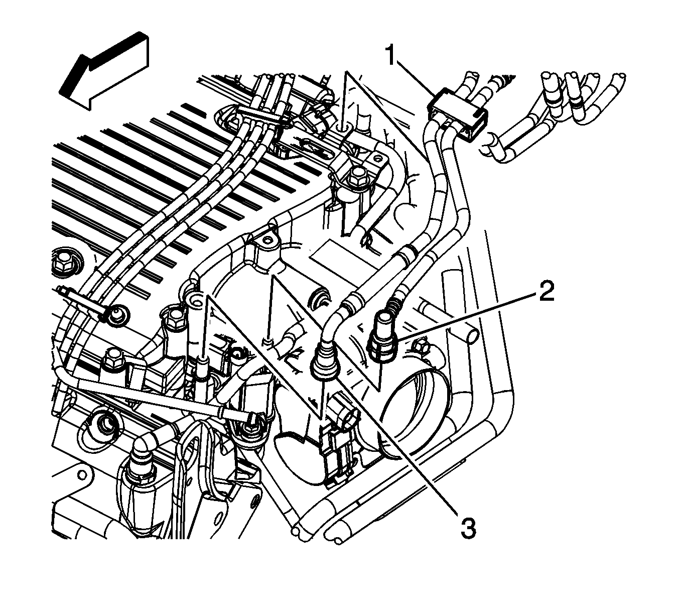
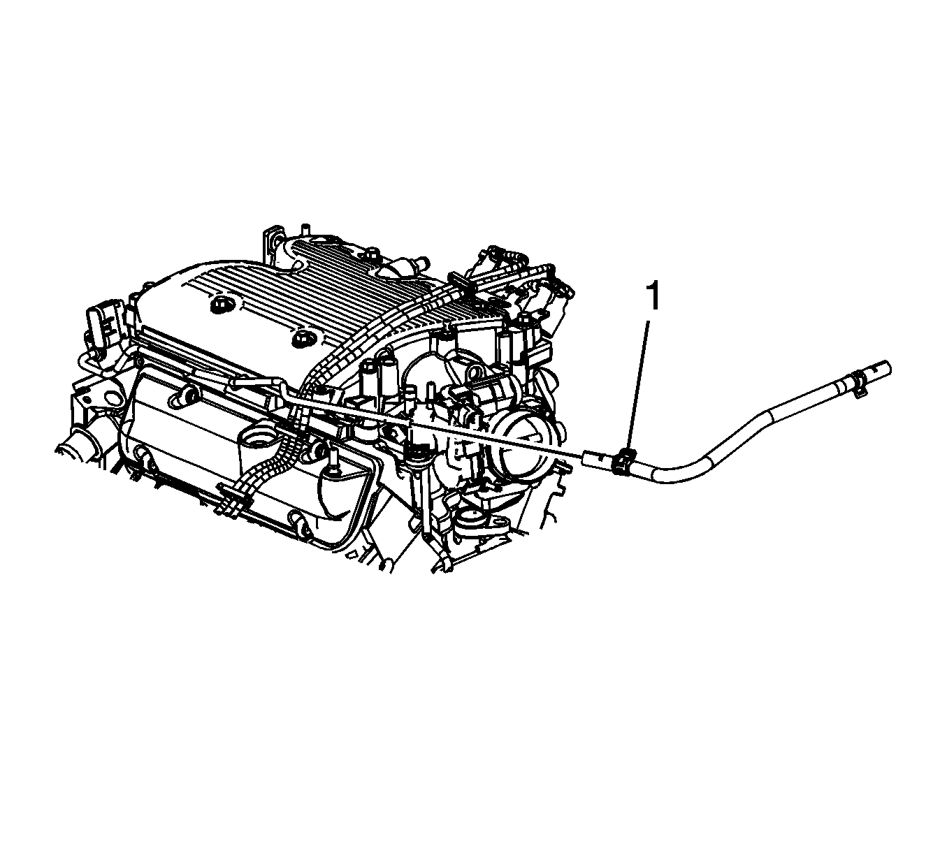
- Disconnect the fuel feed pipe quick connect fitting (3) from the fuel rail. Refer to Metal Collar Quick Connect Fitting Service .
- Disconnect the evaporative emission (EVAP) pipe quick connect fitting (2) from the purge solenoid. Refer to Plastic Collar Quick Connect Fitting Service .
- Remove the fuel line clip (1) from the manifold absolute pressure (MAP) sensor bracket.
- Reposition the fuel/EVAP lines out of the way.
- Drain the cooling system. Refer to Cooling System Draining and Filling .
- Remove the air cleaner outlet duct. Refer to Air Cleaner Outlet Duct Replacement .
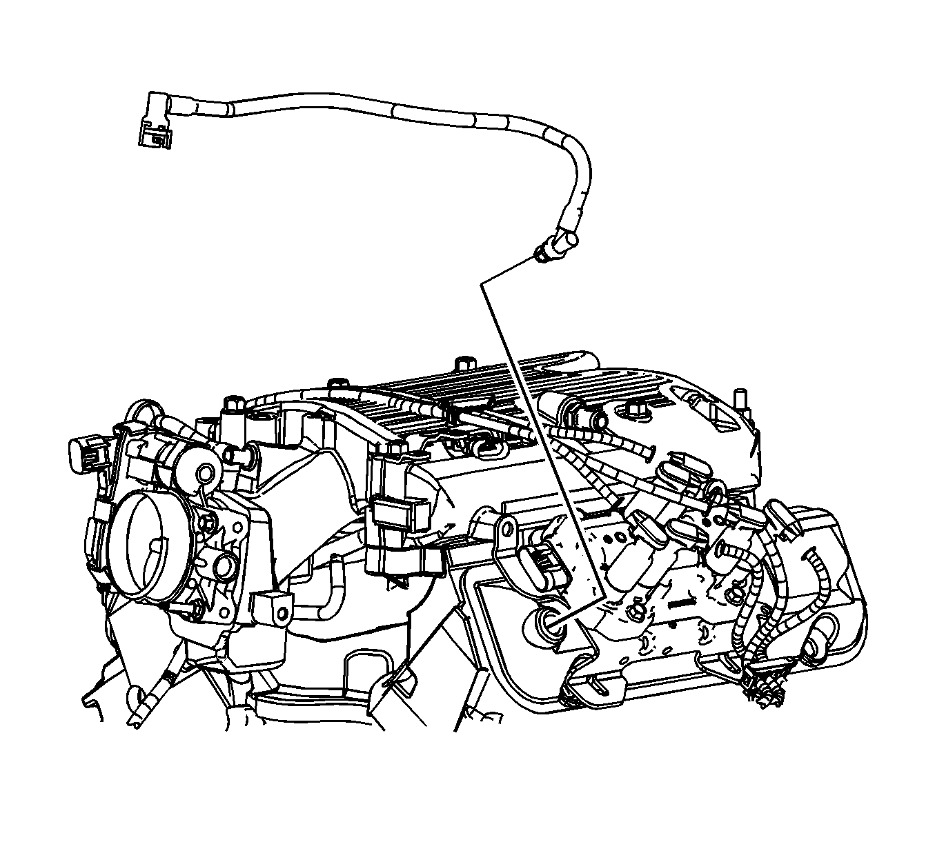
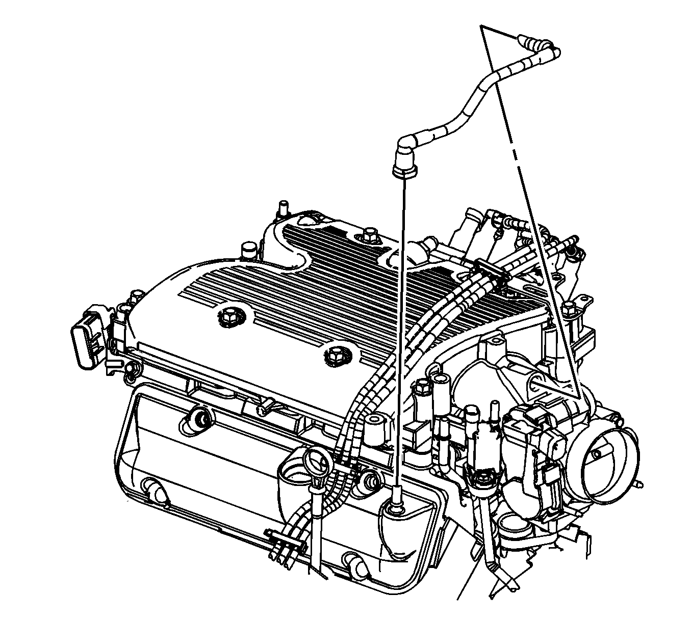
- Remove the positive crankcase ventilation (PCV) fresh air tube from the rocker cover.
- Remove the PCV foul air tube quick connect fitting from the rocker cover. Refer to Plastic Collar Quick Connect Fitting Service .
- Remove the PCV foul air tube from the intake manifold.
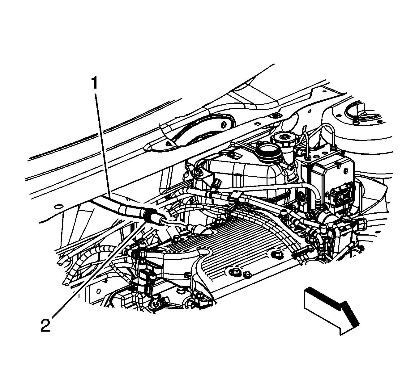
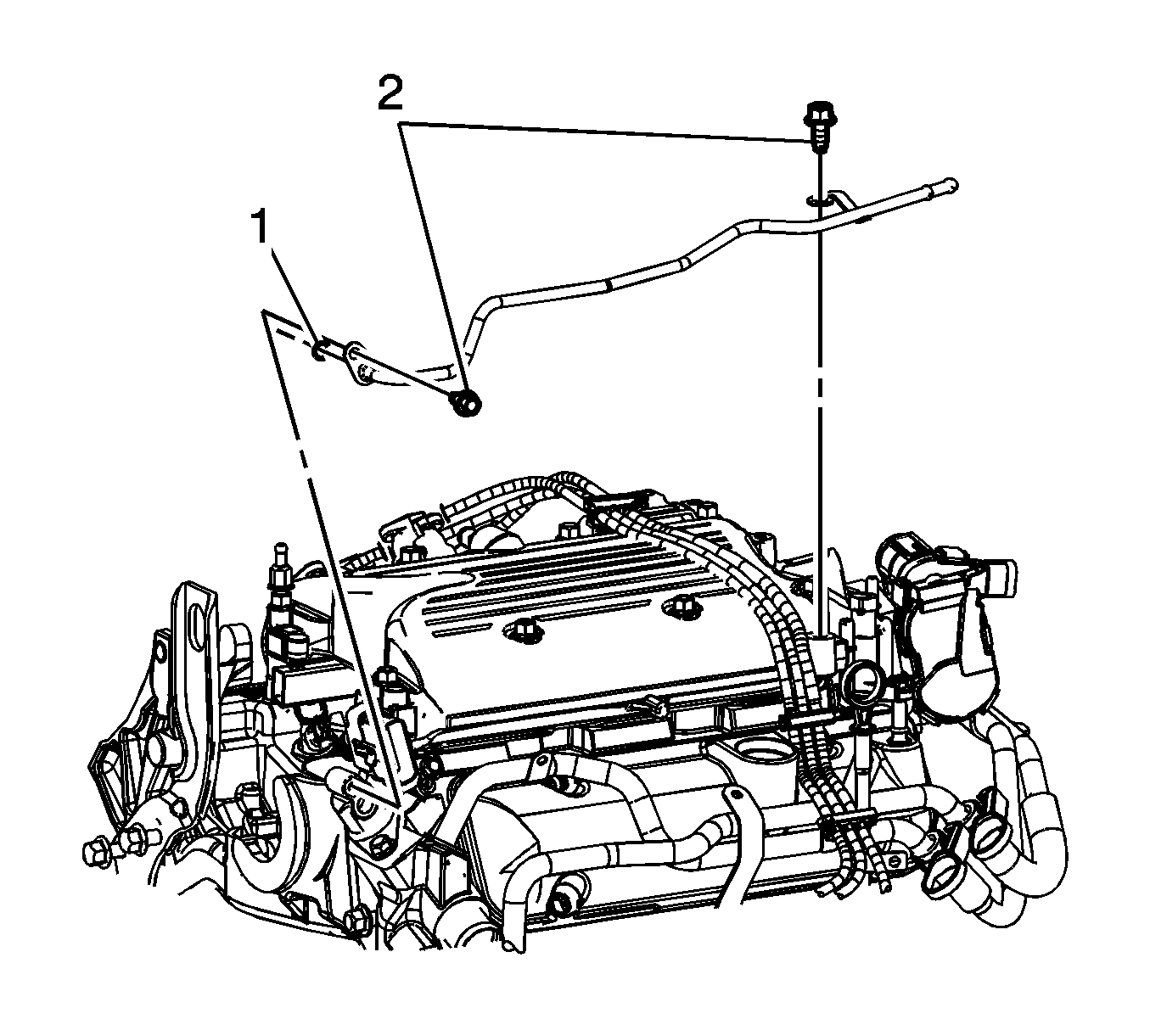
- Reposition the brake booster vacuum hose clamp (2) at the intake manifold.
- Remove the brake booster vacuum hose (1) from the intake manifold.
- Reposition the radiator surge tank inlet hose clamp (1).
- Remove the radiator surge tank inlet hose from the inlet pipe.
- Remove the radiator surge tank inlet pipe bolts (2).
- Remove the radiator surge tank inlet pipe.
- Remove and discard the O-ring seal (1).
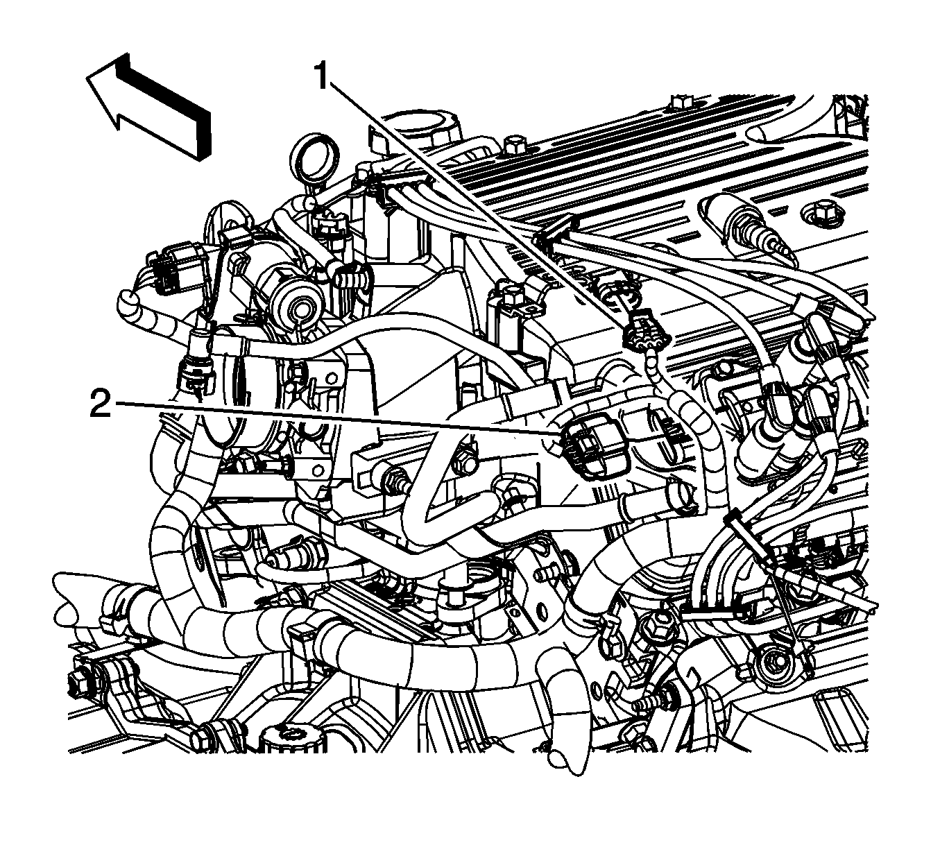
- Disconnect the engine wiring harness electrical connector (1) from the MAP sensor.
- Disconnect the engine wiring harness electrical connector (1) from the EVAP canister purge solenoid.
- Disconnect the engine wiring harness electrical connector (2) from the electronic throttle control (ETC).
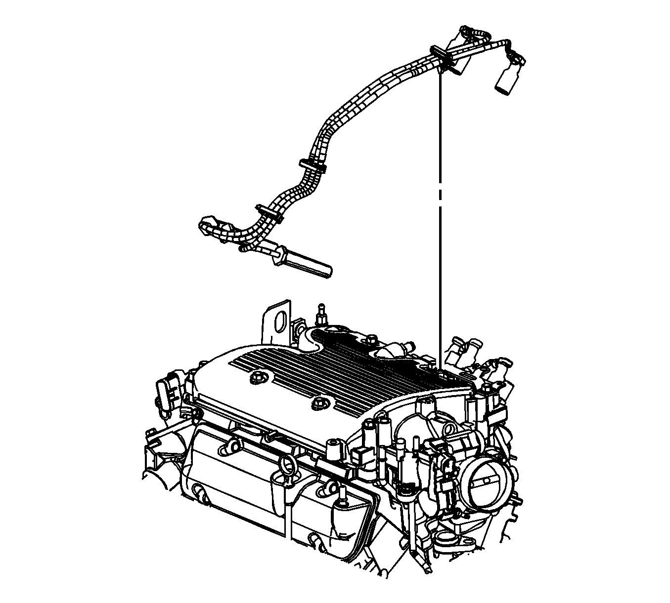
- Disconnect the left side spark plug wires from the spark plugs.
- Disconnect the left side spark plug wires from the ignition coil.
- Disengage the spark plug wire retainer clips from the heater inlet and outlet pipe bracket and the MAP sensor bracket.
- Remove the left side spark plug wires.
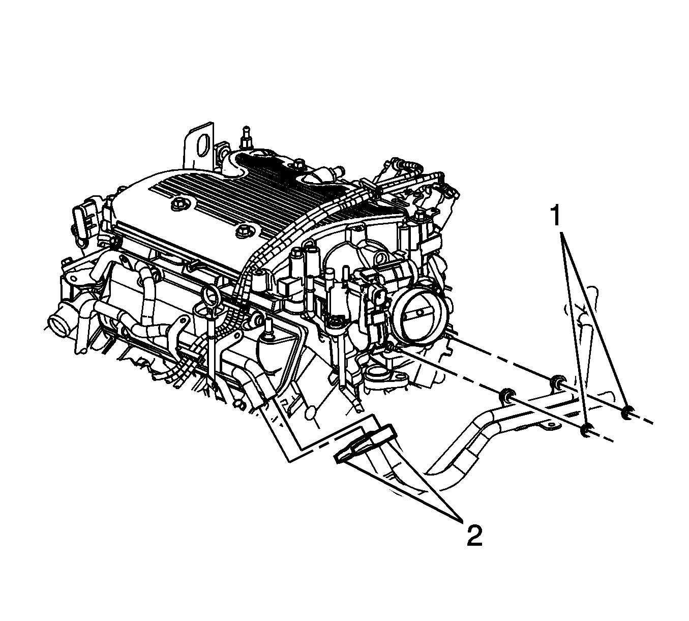
- Remove the heater inlet and outlet pipe nuts (1) from the throttle body studs.
- Reposition the heater inlet and outlet hose clamps (2) from the pipes.
- Remove the heater inlet and outlet hoses from the heater inlet and outlet pipes.
- Remove the heater inlet and outlet pipe bracket from the throttle body studs. Reposition the inlet and outlet pipe out of the way.
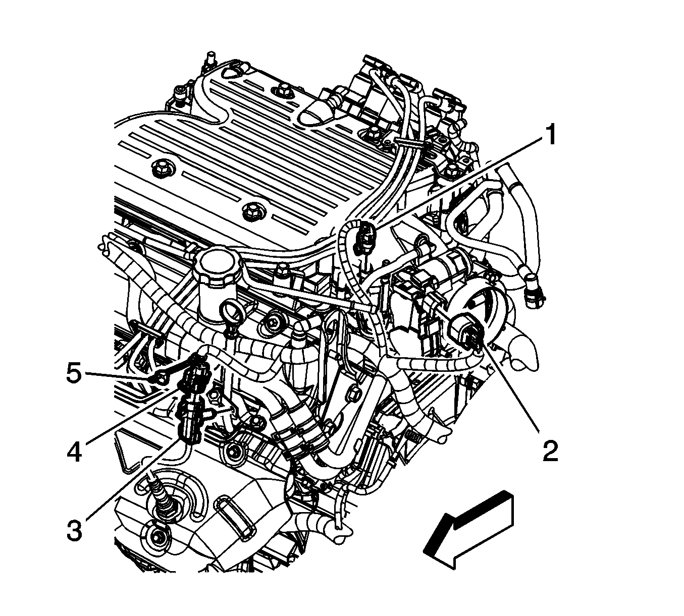
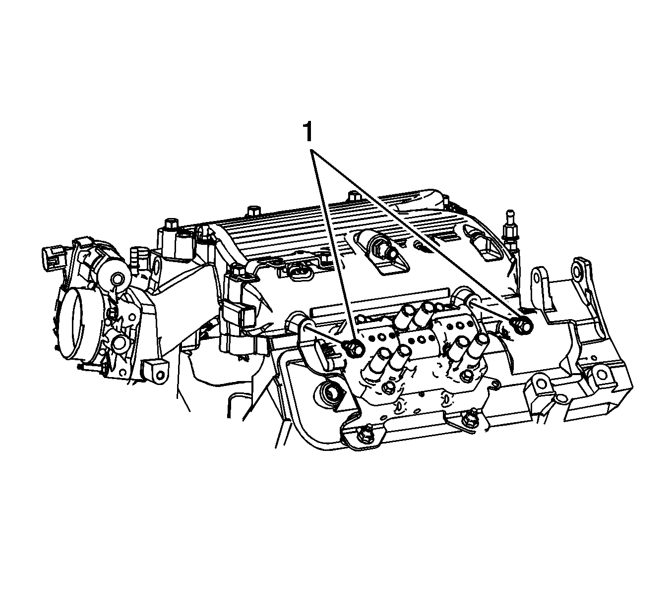
- Remove the ignition coil bracket bolts (1).
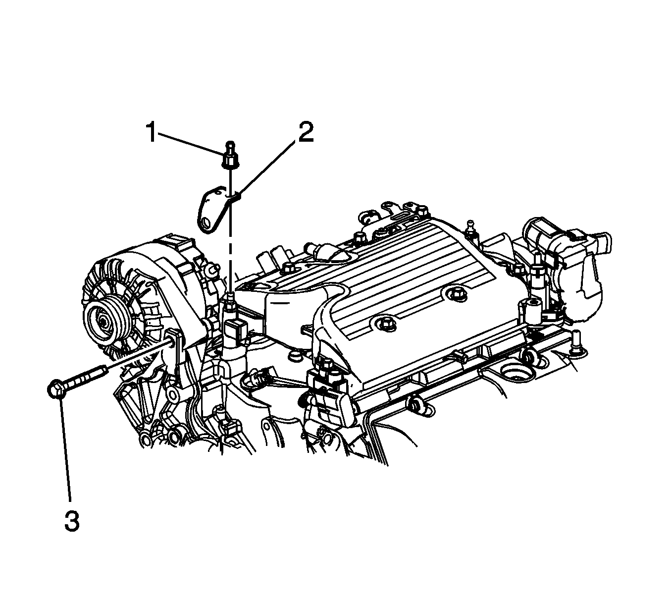
- Remove the generator rear brace upper nut (1).
- Remove the generator through bolt (3).
- Remove the generator rear brace (2).
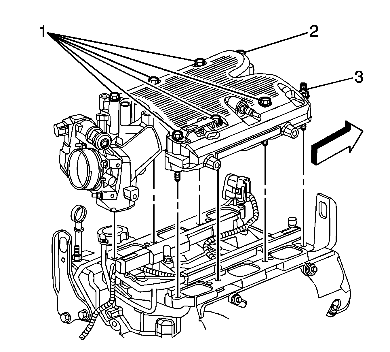
- Remove the upper intake manifold bolts (1, 2) and stud (3).
- Separate and remove the upper intake manifold from the lower intake manifold.
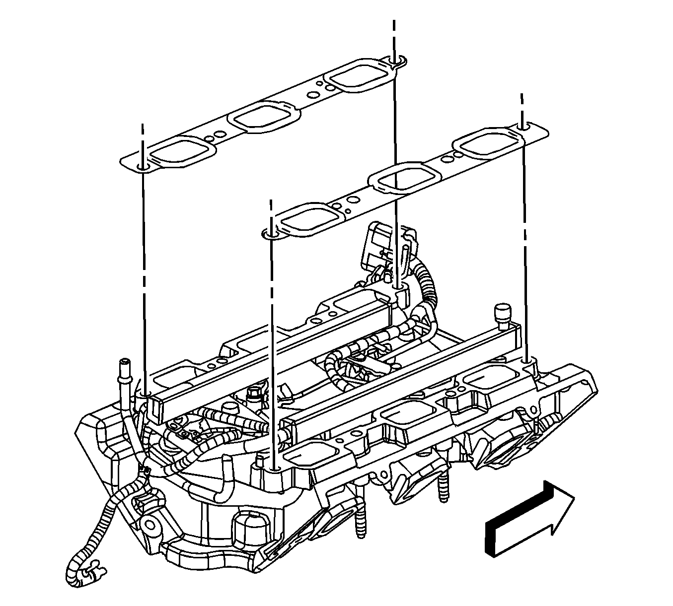
- Remove the upper to lower intake manifold gaskets.
- If replacing the upper intake manifold, perform the following steps otherwise proceed to step 8 in the Installation Procedure.
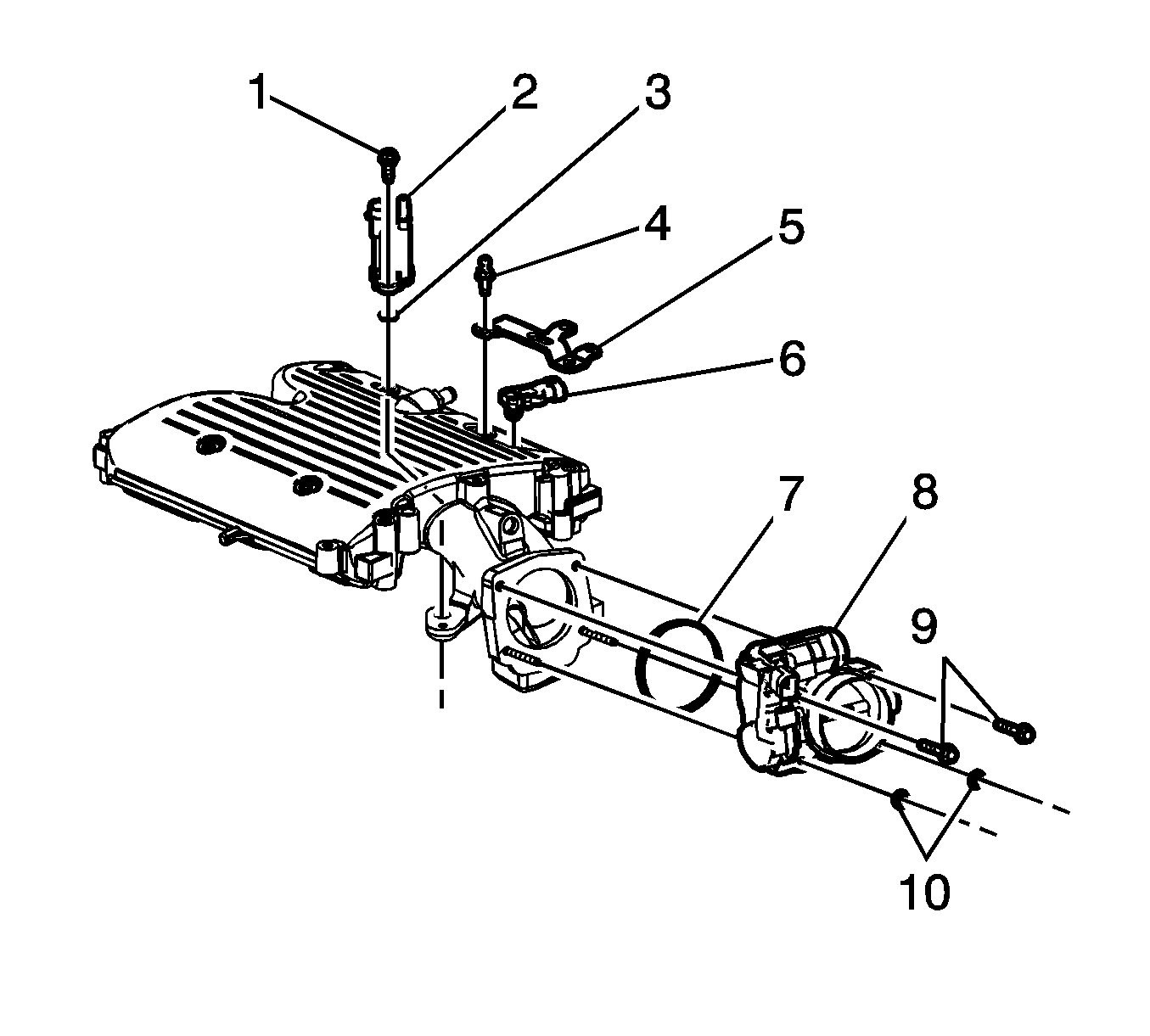
- Remove the EVAP canister purge solenoid valve bolt (1), valve (2).
- Remove and discard the EVAP canister purge solenoid O-ring seal (3).
- Remove the intake manifold cover ball stud (4).
- Remove the MAP sensor bracket (5) and MAP sensor (6).
- Remove the throttle body bolts (9) and nuts (10).
- Remove the throttle body (8) and throttle body O-ring seal (7).
Installation Procedure
- If replacing the upper intake manifold, perform the following steps otherwise proceed to step 8.
- Install a NEW throttle body O-ring seal (7) into the groove on the throttle body and install the throttle body (8).
- Install the throttle body bolts (9) and nuts (10).
- Lubricate the MAP sensor seal and install the MAP sensor (6), place the bracket (5) into position.
- Install the intake manifold cover ball stud (4).
- Lubricate and install a NEW EVAP canister purge solenoid O-ring seal (3) onto the solenoid.
- Install the EVAP canister purge solenoid valve (2) and bolt (1).
- Install the NEW upper to lower intake manifold gaskets.
- Set the upper intake manifold onto the lower intake manifold.
- Apply threadlock to the upper intake manifold bolts/stud threads. Refer to Adhesives, Fluids, Lubricants, and Sealers .
- Install the upper intake manifold bolts (1, 2) and stud (3).
- Place the generator rear brace (2) onto the stud.
- Install the generator through bolt (3) until snug.
- Install the generator rear brace upper nut (1) until snug.
- Install the ignition coil bracket bolts (1).
- Position the inlet and outlet pipe and install the heater inlet and outlet pipe bracket to the throttle body studs.
- Install the heater inlet and outlet hoses to the heater inlet and outlet pipes.
- Position the heater inlet and outlet hose clamps (2) to the pipes.
- Install the heater inlet and outlet pipe nuts (1) to the throttle body studs.
- Install the left side spark plug wires.
- Connect the left side spark plug wires to the spark plugs.
- Connect the left side spark plug wires to the ignition coil.
- Engage the spark plug wire retainer clips to the heater inlet and outlet pipe bracket and the MAP sensor bracket.
- Connect the engine wiring harness electrical connector (1) to the EVAP canister purge solenoid.
- Connect the engine wiring harness electrical connector (2) to the ETC.
- Connect the engine wiring harness electrical connector (1) to the MAP sensor.
- Install a NEW O-ring seal (1) to the inlet pipe.
- Install the radiator surge tank inlet pipe.
- Install the radiator surge tank inlet pipe bolts (2).
- Install the radiator surge tank inlet hose to the inlet pipe.
- Position the radiator surge tank inlet hose clamp (1).
- Install the brake booster vacuum hose (1) to the intake manifold.
- Position the brake booster vacuum hose clamp (2) at the intake manifold.
- Install the PCV foul air tube to the intake manifold.
- Install the PCV foul air tube quick connect fitting to the rocker cover. Refer to Plastic Collar Quick Connect Fitting Service .
- Install the PCV fresh air tube to the rocker cover.
- Install the air cleaner outlet duct. Refer to Air Cleaner Outlet Duct Replacement .
- Fill the cooling system. Refer to Cooling System Draining and Filling .
- Position the fuel/EVAP lines.
- Install the fuel line clip (1) to the MAP sensor bracket.
- Connect the fuel feed pipe quick connect fitting (3) to the fuel rail. Refer to Metal Collar Quick Connect Fitting Service .
- Connect the EVAP pipe quick connect fitting (2) to the purge solenoid. Refer to Plastic Collar Quick Connect Fitting Service .
- Install the intake manifold cover. Refer to Intake Manifold Cover Replacement .
- Connect the negative battery cable. Refer to Battery Negative Cable Disconnection and Connection .

Notice: Refer to Fastener Notice in the Preface section.
Tighten
Tighten the bolts/nuts to 10 N·m (89 lb in).
Tighten
Tighten the ball stud to 10 N·m (89 lb in).
Tighten
Tighten the bolt to 12 N·m (106 lb in).


Tighten
Tighten the bolts/stud to 25 N·m (18 lb ft).

Tighten
| • | Tighten the generator through bolt to 50 N·m (37 lb ft). |
| • | Tighten the generator rear brace upper nut to 25 N·m (18 lb ft). |

Tighten
Tighten the bolts to 25 N·m (18 lb ft).

Tighten
Tighten the nuts to 10 N·m (89 lb in).


Tighten
Tighten the bolts to 10 N·m (89 lb in).


