For 1990-2009 cars only
Removal Procedure
- Disconnect the negative battery cable. Refer to Battery Negative Cable Disconnection and Connection.
- Remove the closeout/insulator panel. Refer to Instrument Panel Insulator Panel Replacement - Right Side.
- Remove the knee bolster. Refer to Knee Bolster Replacement.
- Remove the hinge pillar trim panel. Refer to Body Hinge Pillar Trim Panel Replacement.
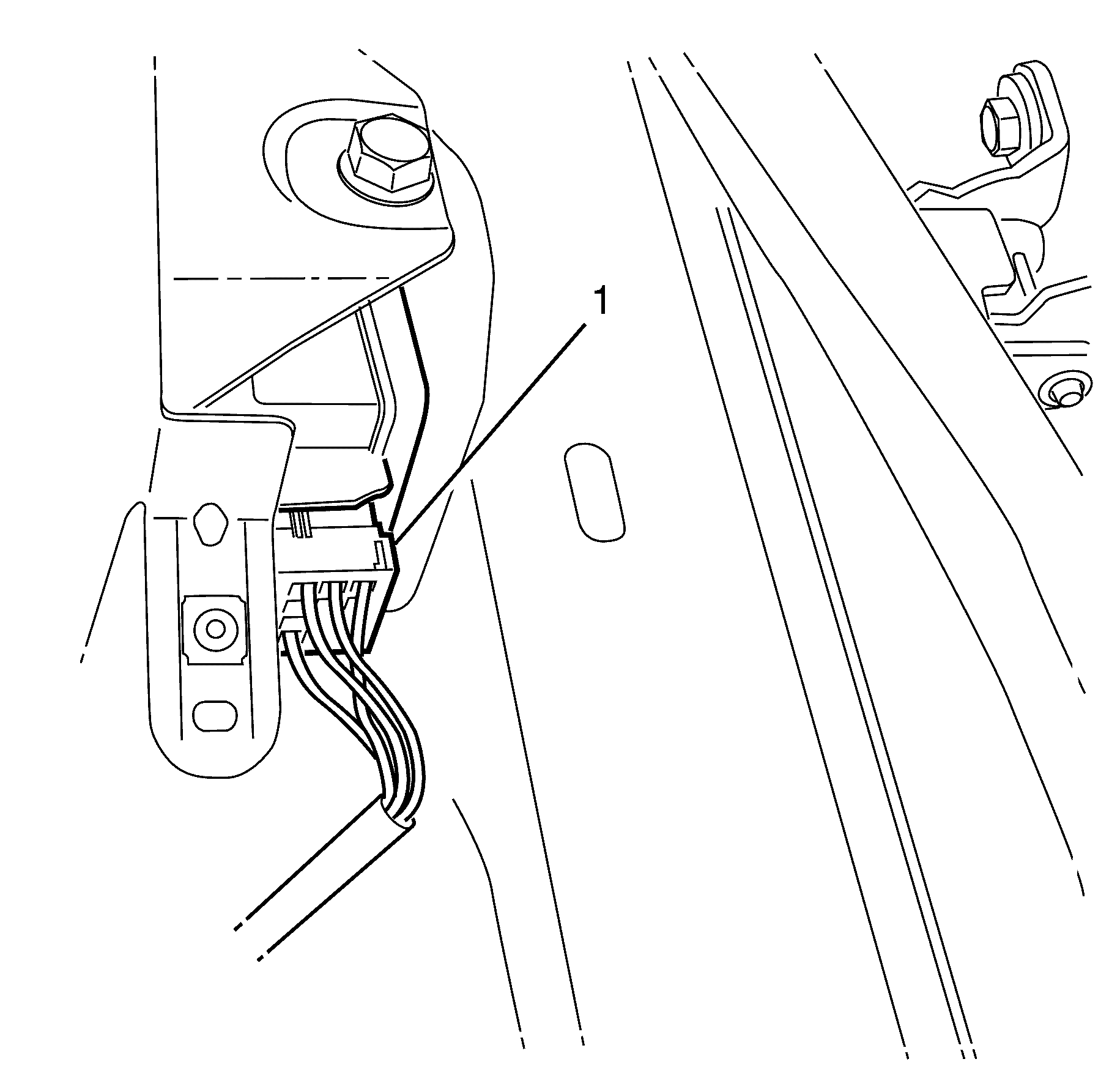
- Disconnect the door module electrical connector (1).
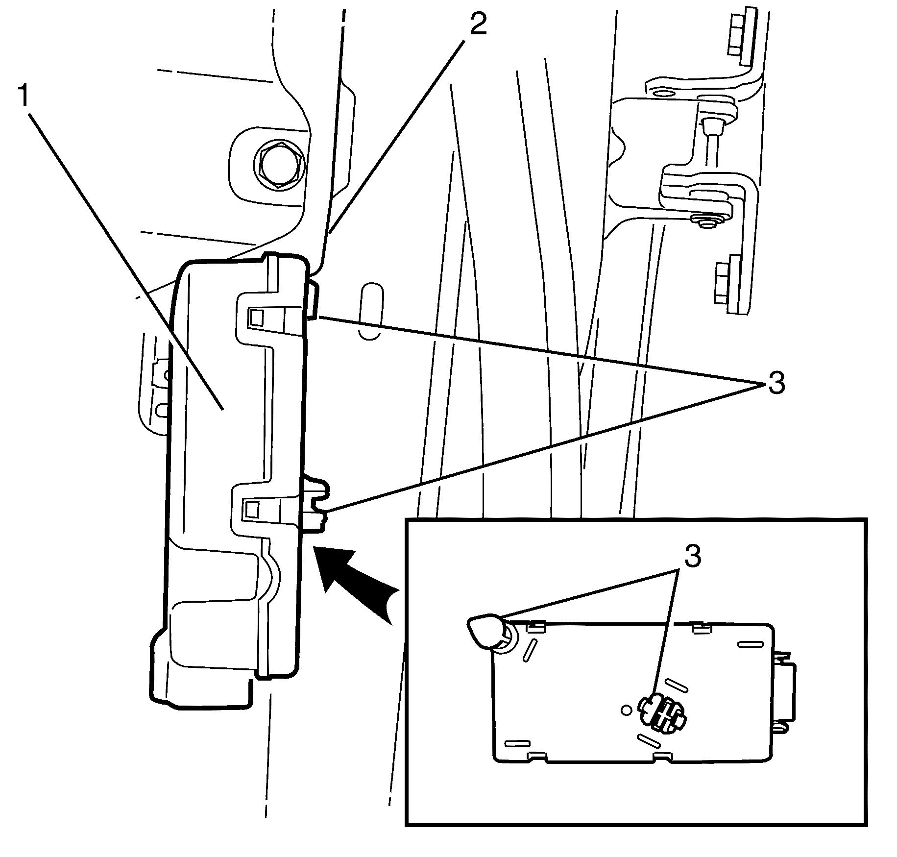
- Pry the door module (1) with a suitable flat bladed tool to release the retainers (3).
- Remove the door module (1) from the vehicle (2).
Caution: Refer to Safety Glasses Caution in the Preface section.


Important: The door module is located on the right side just under the instrument panel attached to the body.
Important: Pry the door module (1) with a suitable flat bladed tool then manoeuvre to release top locating retainer (3).
Installation Procedure
- Position the door module (1) to the vehicle (2).
- Install the door module (1) and push to secure the retainers (3).
- Connect the door module electrical connector (1).
- Install the hinge pillar trim panel. Refer to Body Hinge Pillar Trim Panel Replacement.
- Install the knee bolster. Refer to Knee Bolster Replacement.
- Install the closeout/insulator panel. Refer to Instrument Panel Insulator Panel Replacement - Right Side.
- Connect the negative battery cable. Refer to Battery Negative Cable Disconnection and Connection.
- If re-programming is required. Refer to Control Module References.

Important: Locate the top retainer first then press to engage the lower retainer.

