Removal Procedure
- Remove the engine cover. Refer to Engine Cover Replacement in Interior Trim.
- Remove the air cleaner . Refer to Air Cleaner Replacement .
- Disconnect the negative battery cable. Refer to Battery Negative Cable Disconnection and Connection in Engine Electrical.
- Remove the fuel filter and element housing. Refer to Fuel Filter Assembly Replacement .
- Remove the water outlet tube. Refer to Water Outlet Tube Replacement in Engine Cooling.
- Remove the charged air cooler inlet pipe from the turbocharger. Refer to Charged Air Cooler Hoses/Pipes Replacement in Engine Mechanical - 6.6L (LLY).
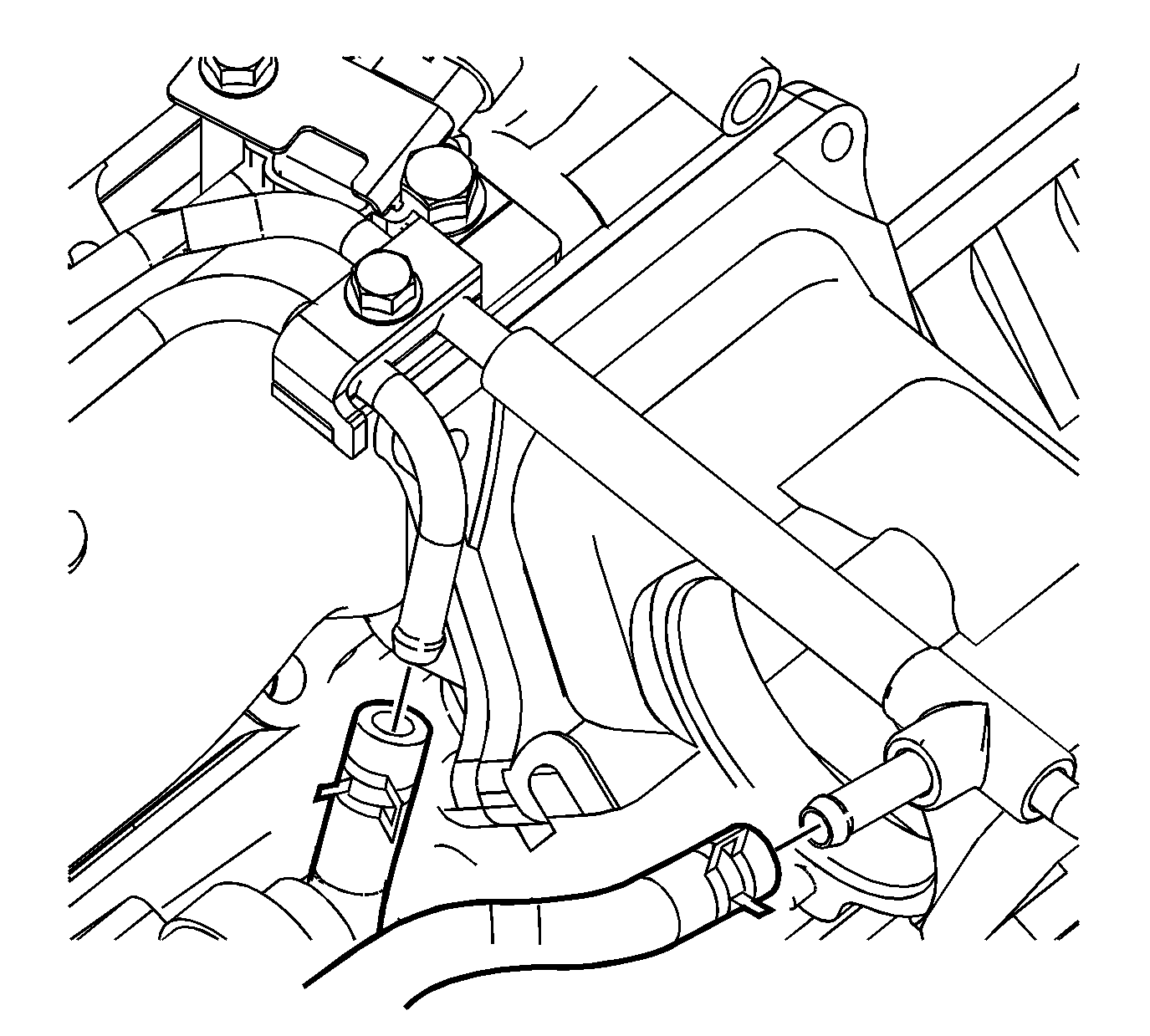
- Disconnect the fuel feed and return line quick connect fittings. Refer to Metal Collar Quick Connect Fitting Service .
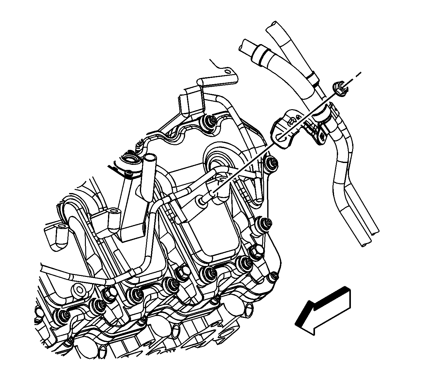
- Remove the fuel line bracket nut.
- Remove the fuel line bracket from the stud.
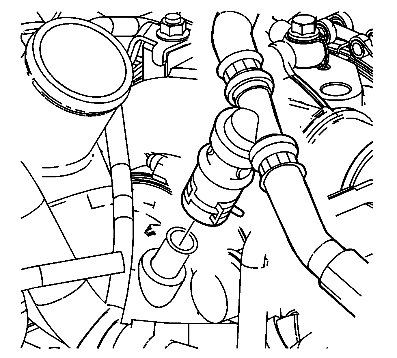
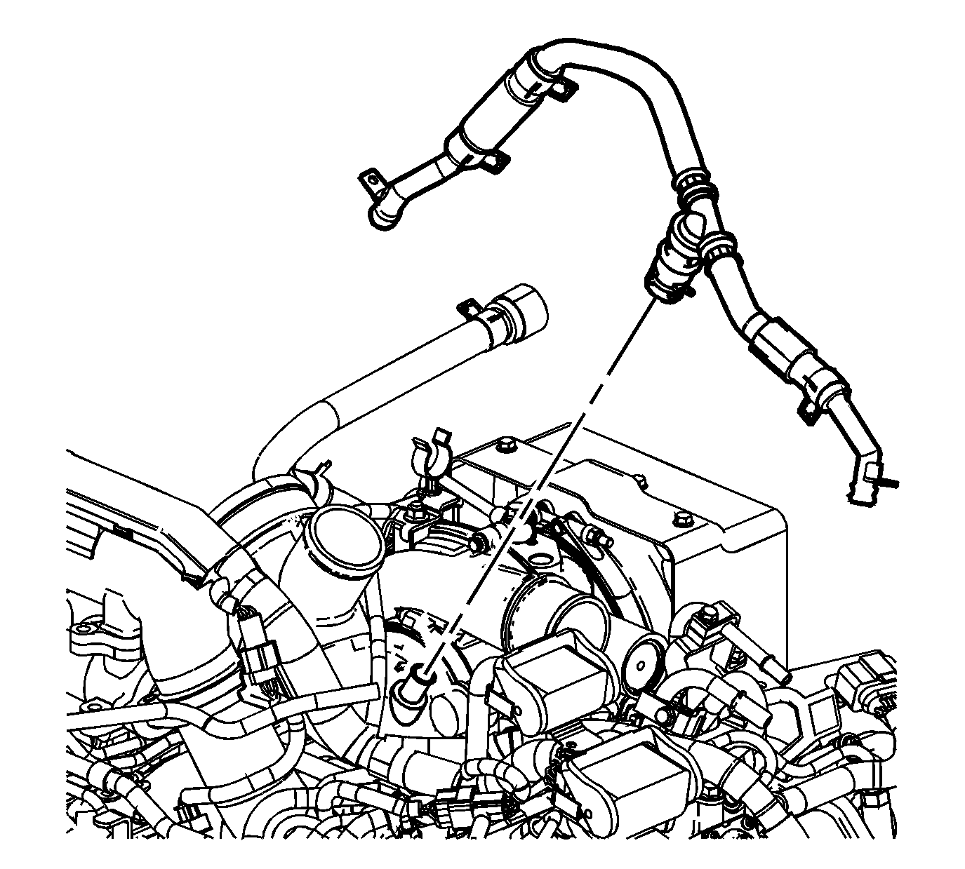
- Reposition the left positive crankcase ventilation (PCV) hose clamp at the resonator tee.
- Remove the left PCV hose from the tee.
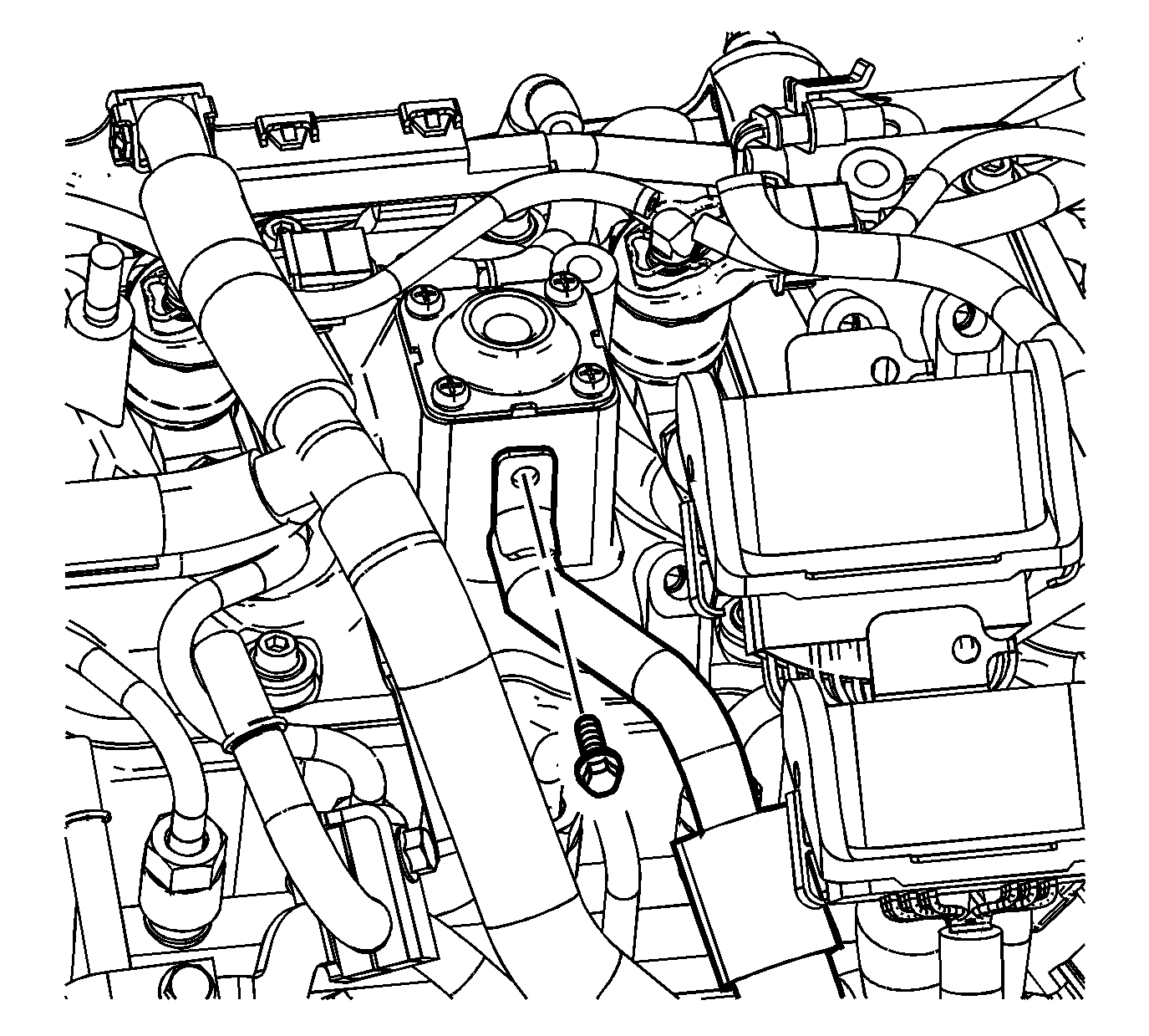
- Remove the left PCV hose/pipe bolt.
- Remove the left PCV hose/pipe.
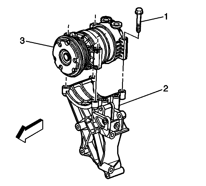
- Remove the air conditioning (A/C) compressor bolts (1) and the A/C compressor (3) from the bracket (2).
- Reposition the A/C compressor aside.
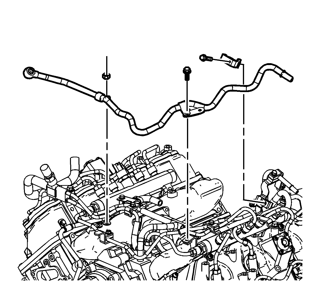
- Remove the banjo bolt and washer from the fuel injection control module.
- Remove the fuel feed pipe nuts/bolts.
- Remove the fuel feed pipe.
- Disconnect the fuel rail balance pipe from the fuel rails.
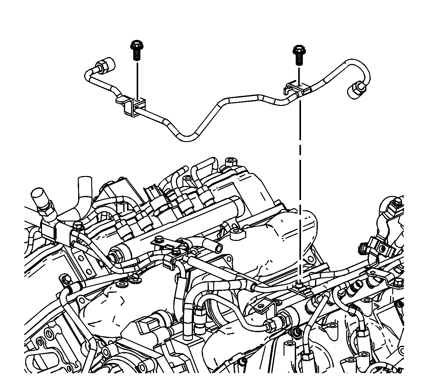
- Remove the fuel rail balance pipe bolts.
- Remove the fuel rail balance pipe.
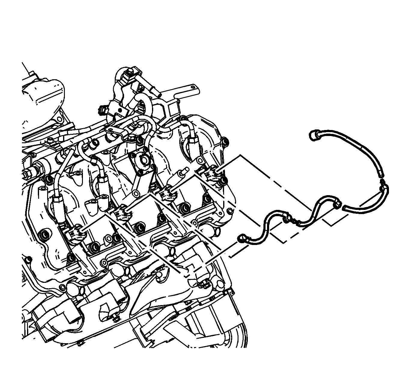
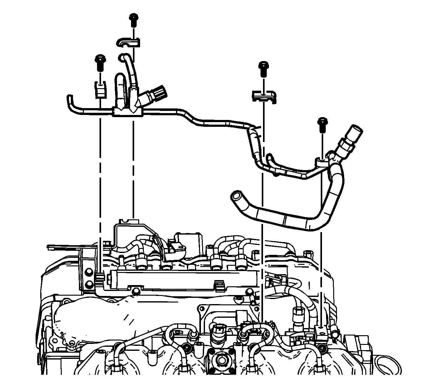
- Disconnect the fuel injector return hose from the distribution block line.
- Reposition the distribution block hose clamps at the injection pump.
- Remove the fuel hoses from the distribution block.
- Reposition the distribution block hose clamp at the rear of the left fuel rail.
- Remove the fuel hose from the fuel rail.
- Remove the distribution block fuel line clip bolts.
- Remove the distribution block and lines.
- Remove the fuel pipe bracket bolts.
- Remove the fuel pipe bracket.
- Disconnect the fuel inlet pipe from the fuel rail.
- Disconnect the fuel inlet pipe from the injection pump.
- Remove the inlet fuel pipe.
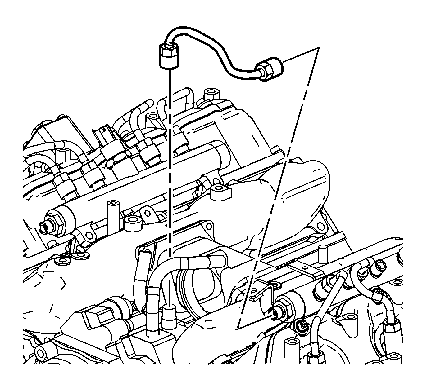
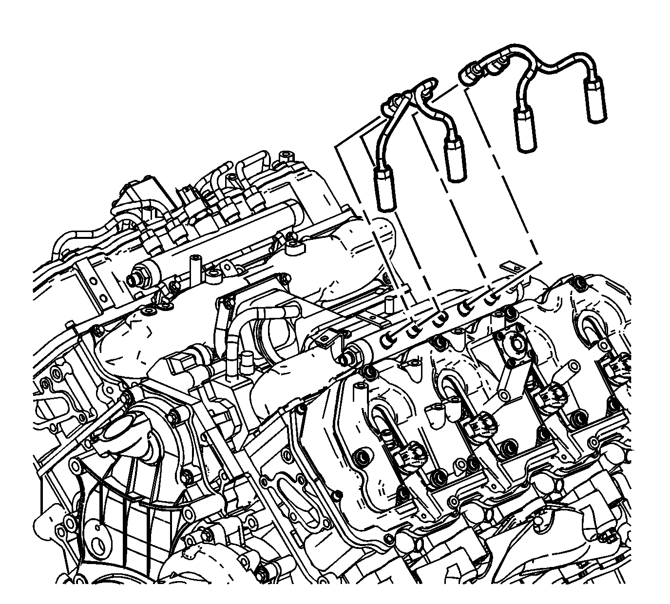
- Remove the fuel injector pipes.
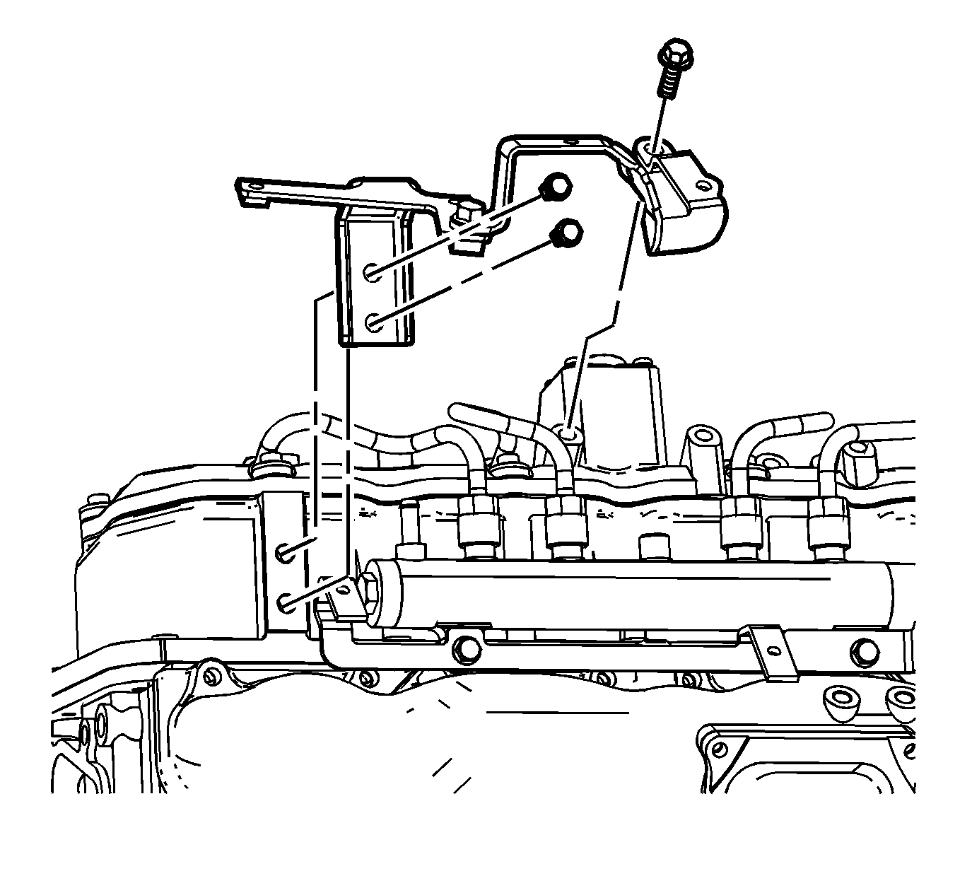
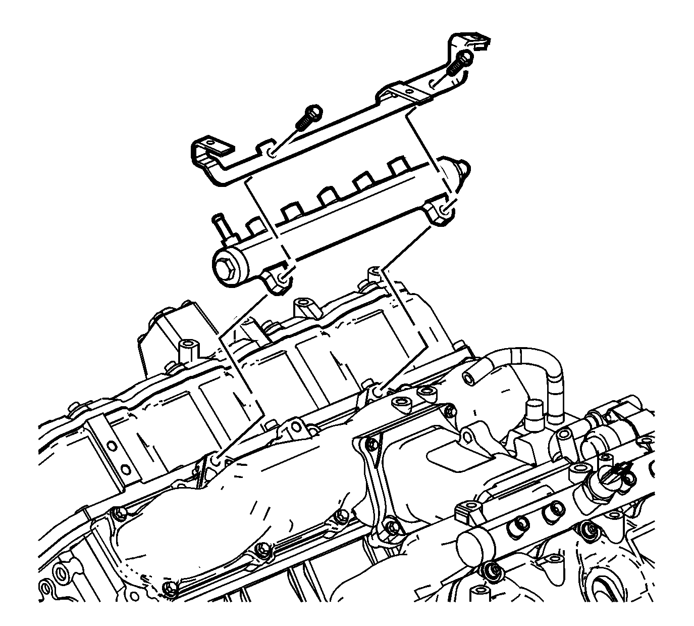
- Remove the fuel rail bolts.
- Remove the fuel rail and bracket.
Important: After removing the charged air cooler duct, cover the turbocharger opening with tape in order to prevent entry of objects.
Installation Procedure
- Install the fuel rail and bracket.
- Install the fuel rail bolts.
- Install the fuel injector pipes.
- Remove the inlet fuel pipe.
- Connect the fuel inlet pipe to the injection pump.
- Connect the fuel inlet pipe to the fuel rail.
- Install the fuel pipe bracket.
- Install the fuel pipe bracket bolts.
- Install the distribution block and lines.
- Install the distribution block fuel line clip bolts.
- Install the fuel hose to the fuel rail.
- Position the distribution block hose clamp at the rear of the left fuel rail.
- Install the fuel hoses to the distribution block.
- Position the distribution block hose clamps at the injection pump.
- Connect the fuel injector return hose to the distribution block line.
- Install the fuel rail balance pipe.
- Connect the fuel rail balance pipe to the fuel rails.
- Install the fuel rail balance pipe bolts.
- Install the fuel feed pipe.
- Install the fuel feed pipe nut/bolt.
- Install the banjo bolt and washer to the fuel injection control module.
- Position the A/C compressor (3) onto the bracket (2).
- Install the A/C compressor bolts (1).
- Install the left PCV hose/pipe.
- Install the left PCV hose/pipe bolt.
- Install the left PCV hose to the tee.
- Position the left PCV hose clamp at the resonator tee.
- Install the fuel line bracket to the stud.
- Install the fuel line bracket nut.
- Connect the fuel feed and return line quick connect fittings. Refer to Metal Collar Quick Connect Fitting Service .
- Remove the tape from the turbocharger openings.
- Install the charged air cooler inlet pipe to the turbocharger. Refer to Charged Air Cooler Hoses/Pipes Replacement in Engine Mechanical - 6.6L (LLY).
- Install the water outlet tube. Refer to Water Outlet Tube Replacement in Engine Cooling.
- Install the fuel filter and element housing. Refer to Fuel Filter Assembly Replacement .
- Connect the negative battery cable. Refer to Battery Negative Cable Disconnection and Connection in Engine Electrical.
- Install the air cleaner . Refer to Air Cleaner Replacement .
- Install the engine cover. Refer to Engine Cover Replacement in Interior Trim.
- Prime the fuel system. Refer to Fuel System Priming .
- Start the engine. If the engine stalls, repeat the above step.
- Once the engine starts, inspect for fuel leaks.
Notice: Refer to Fastener Notice in the Preface section.

Tighten
Tighten the bolts to 25 N·m (18 lb ft).

Tighten
Tighten the fittings to 41 N·m (30 lb ft).

Tighten
Tighten the fittings to 41 N·m (30 lb ft).

Tighten
Tighten the bolts to 25 N·m (18 lb ft).

Tighten
Tighten the bolts 25 N·m (18 lb ft).


Tighten
Tighten the fittings to 41 N·m (30 lb ft).
Tighten
Tighten the bolts 25 N·m (18 lb ft).

Tighten
Tighten the nut/bolt to 25 N·m (18 lb ft).
Tighten
Tighten the bolt to 40 N·m (29 lb ft).

Tighten
Tighten the bolts to 50 N·m (37 lb ft).


Tighten
Tighten the bolt to 18 N·m (13 lb ft).

Tighten
Tighten the nut to 21 N·m (15 lb ft).
Important: Lubricate the end of the duct prior to installation.
