Instrument Panel Lower Trim Panel Replacement Impala
Tools Required
J 38778 Door Trim Pad Clip Remover
Removal Procedure
- Disable the SIR system. Refer to Disabling the SIR System in SIR.
- Disconnect the battery ground cable. Refer to Battery Negative Cable Disconnection and Connection in Engine Electrical.
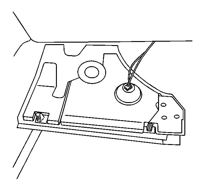
- Release the left instrument panel (I/P) insulator tabs from the lower I/P trim pad retainers.
- Rotate the courtesy lamp counterclockwise in order to disconnect the courtesy lamp from the left I/P insulator.
- Remove the left I/P insulator from the stud at the accelerator pedal.
- Remove the left I/P insulator.
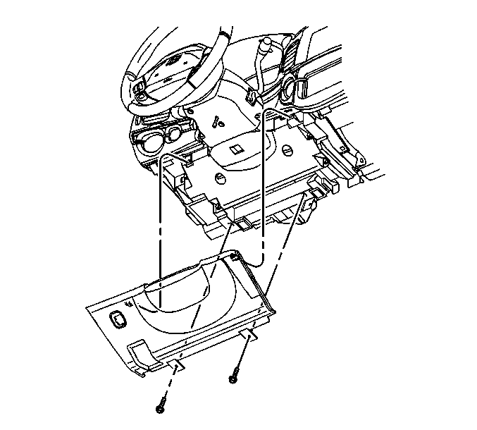
- Remove the bolts from the steering column opening filler panel.
- Release the filler panel retainers from the lower trim panel. Carefully lower the filler panel away from the trim panel.
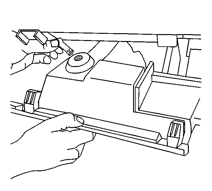
- Disconnect the electrical connector from the rear compartment release switch.
- Remove the steering column opening filler panel.
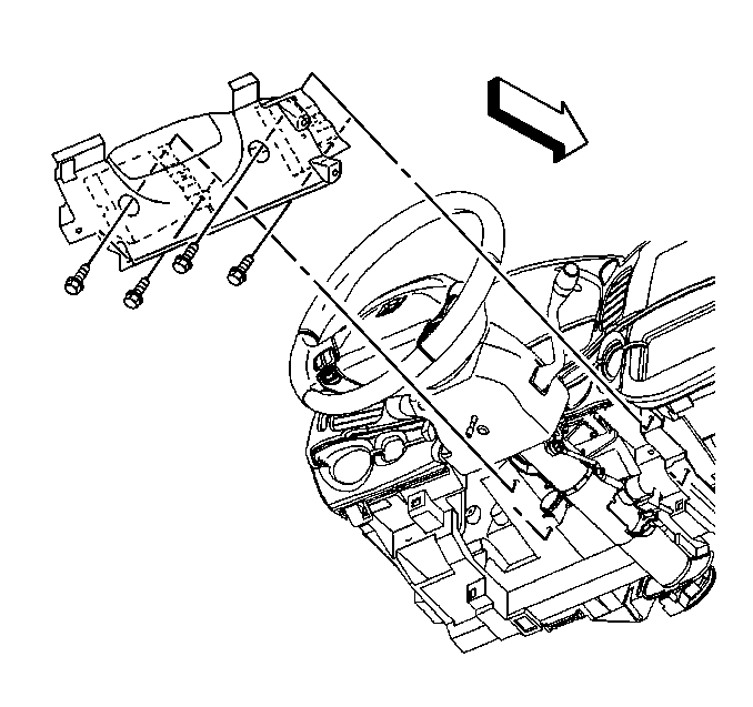
- Remove the 4 bracket screws from the I/P driver knee bolster.
- Remove the knee bolster bolts at the I/P lower trim panel.
- Remove the knee bolster bolts at the instrument carrier. Remove the I/P driver knee bolster.
- Remove the access opening cover from the right I/P.
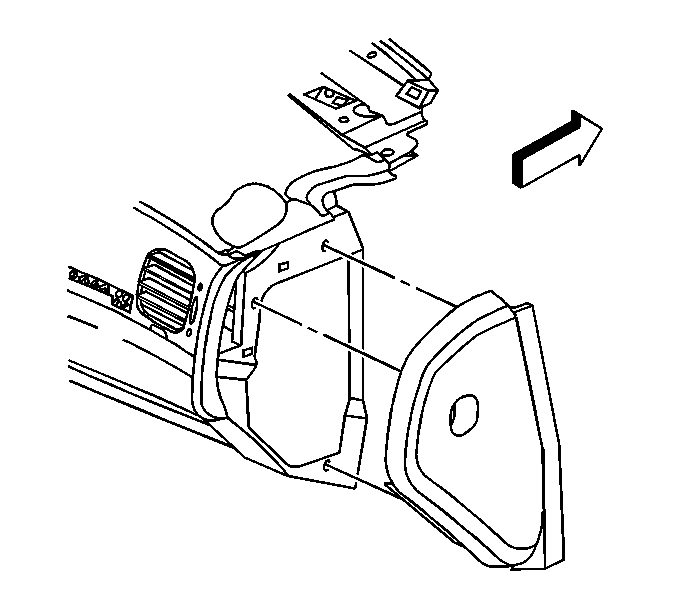
- Use J 38778 in order to remove the push-in retainer from the right I/P insulator.
- Release the right I/P insulator from the I/P lower trim panel retainers.
- Rotate the courtesy lamp counterclockwise in order to remove the lamp from the right I/P insulator.
- Remove the right I/P insulator.
- Remove the I/P compartment screws.
- Open the I/P compartment. Disconnect the damper cable from the I/P compartment tab.
- Carefully remove the I/P compartment.
- Remove the floor console, if equipped. Refer to Front Floor Console Replacement .
- Remove the SIR inflatable module from the steering wheel. Refer to Inflatable Restraint Steering Wheel Module Replacement in SIR.
- Remove the steering wheel. Refer to Steering Wheel Replacement in Steering Wheel and Column.
- Remove the steering column shrouds.
- Remove the multifunction switch. Refer to Multifunction Turn Signal Lever Replacement - On Vehicle in Steering Wheel and Column.
- If the vehicle is equipped with a column shift, engage the parking brake and position the transaxle shift control indicator to position 1.
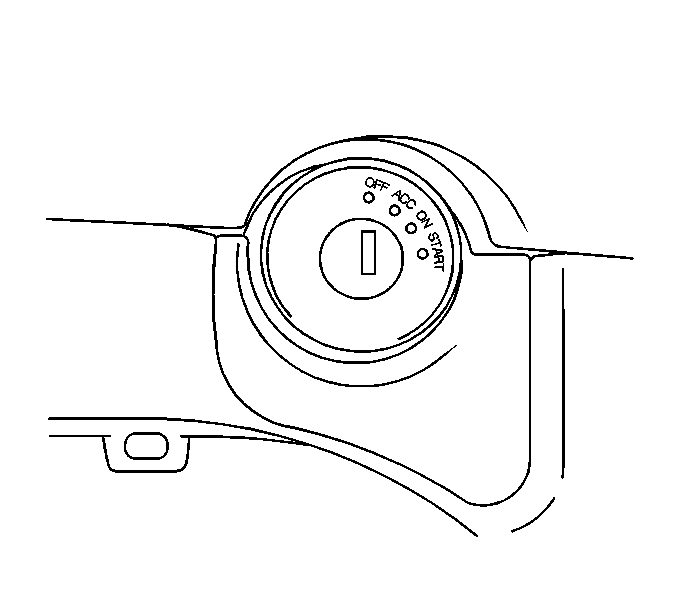
- Using a small, flat-bladed tool, carefully remove the ignition switch cylinder bezel.
- Remove the screws from the I/P cluster trim plate.
- Beginning at the right, grasp the trim plate and carefully pull rearward.
- Continue working around the trim plate until you have released all of the retainers from the trim pad.
- Disconnect the electrical connectors from the hazard switch and from the traction control switch, if equipped.
- Remove the I/P cluster trim plate.
- Remove the ignition switch bolts and reposition the ignition switch. Refer to Ignition and Start Switch Replacement .
- Remove the radio. Refer to Radio Replacement in Entertainment.
- Remove the HVAC control assembly. Refer to Heater and Air Conditioning Control Replacement in HVAC Systems-Manual.
- Remove the headlamp switch. Disconnect the electrical connector from the headlamp switch. Refer to Headlamp Switch Replacement in Lighting Systems.
- Remove the hood latch release handle. Refer to Hood Primary Latch Release Cable Handle Replacement in Body Front End.
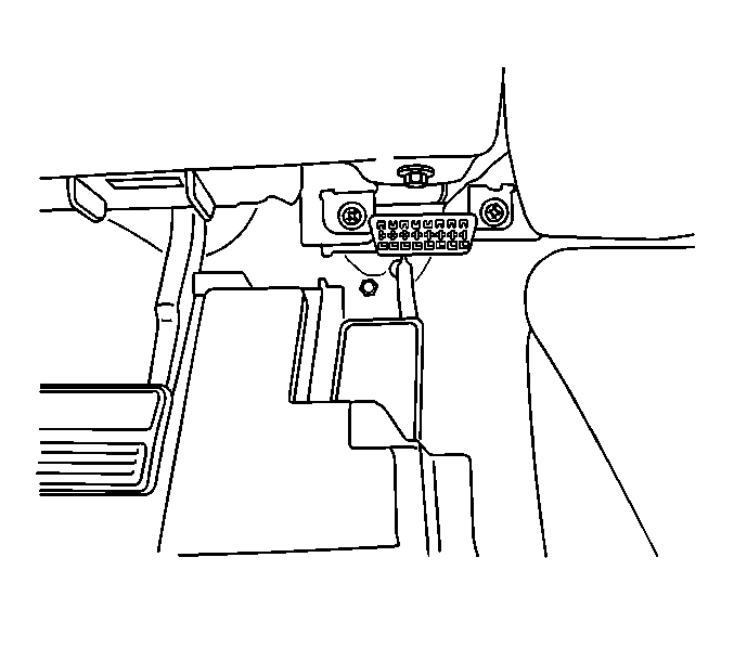
- Disconnect the data link connector.
- Remove the garnish moldings from the left and the right windshield pillar. Refer to Windshield Pillar Garnish Molding Replacement in Interior Trim.
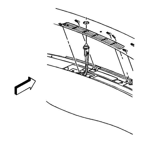
- Starting at the right side, carefully lift upwards on the I/P upper trim panel in order to release the retainers. Continue working to the left until you have released all of the retainers.
- Disconnect the electrical connector from the remote keyless entry (RKE) module.
- Remove the RKE module.
- Disconnect the daytime running lamps sensor from the I/P upper trim panel.
- Remove the I/P upper trim panel.
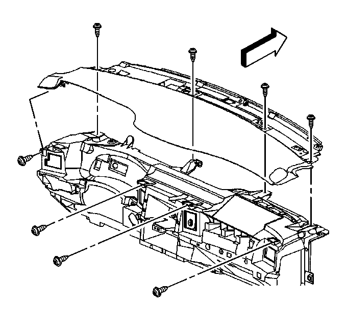
- Remove the I/P upper trim pad screws. Release the retainers to the rear of the windshield.
- Remove the I/P upper trim pad.
- Remove the I/P cluster. Refer to Instrument Cluster Replacement .
- Remove the SIR inflator module. Refer to Inflatable Restraint Instrument Panel Module Replacement in SIR.
- Remove the I/P compartment lamp switch. Refer to Instrument Panel Compartment Lamp Replacement in Lighting Systems.
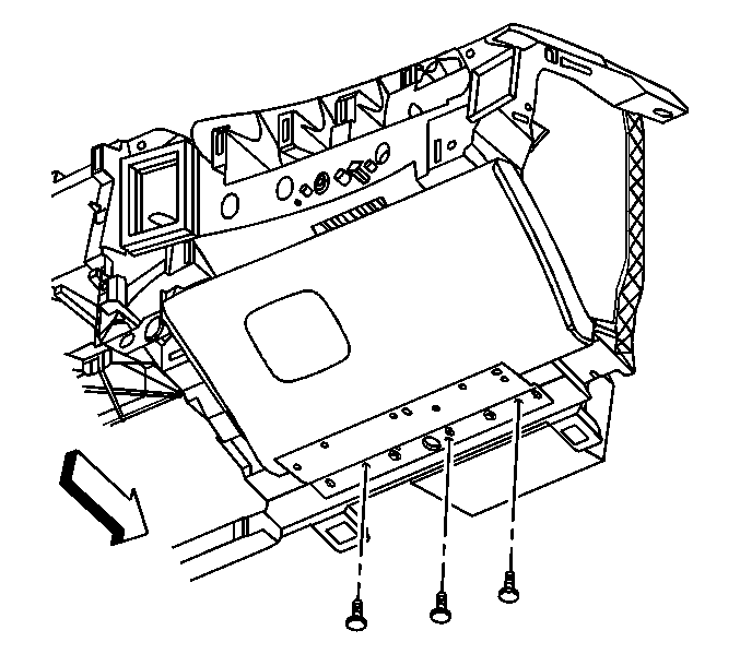
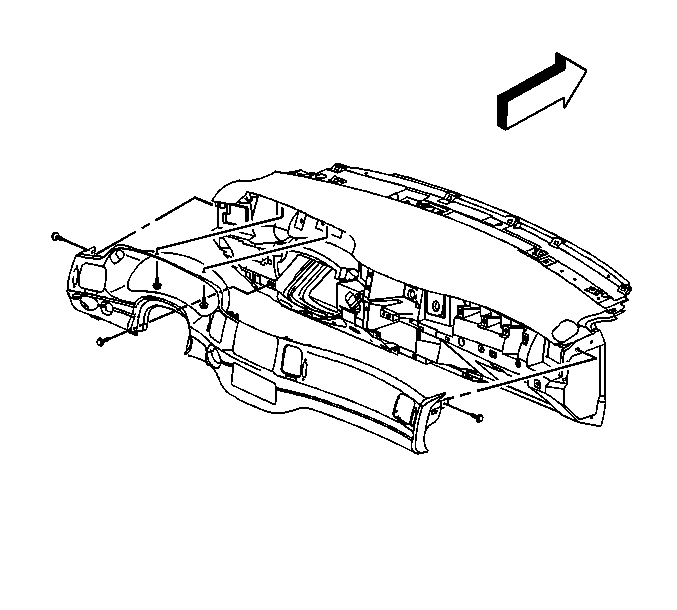
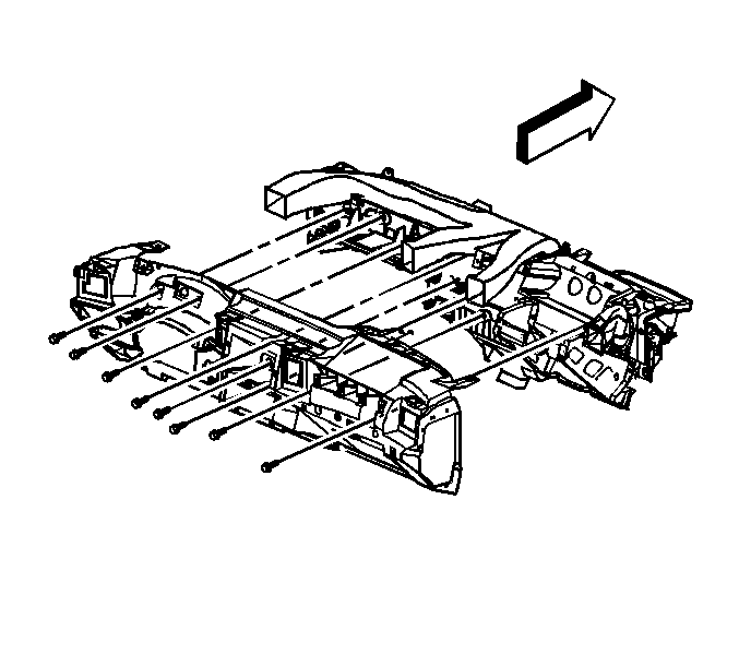
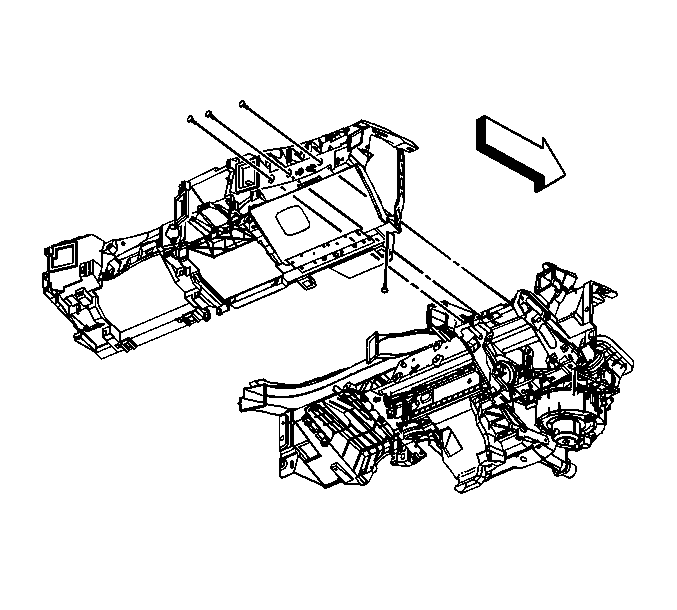
- Remove the screws that secure the I/P lower trim panel to the cross-car beam.
- Reposition the I/P wiring harness.
- Remove the I/P lower trim panel from the vehicle.
Caution: Refer to SIR Caution in the Preface section.
Caution: Refer to Battery Disconnect Caution in the Preface section.
Installation Procedure
- Position the I/P lower trim panel within the vehicle.
- Reposition the I/P wiring harness.
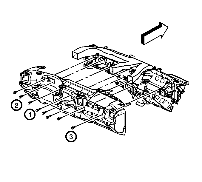
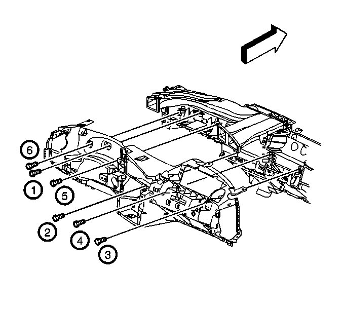
- Install the screws which secure the I/P lower trim panel to the cross vehicle beam in the order indicated in the graphic.
- Install the I/P compartment lamp switch. Refer to Instrument Panel Compartment Lamp Replacement in Lighting Systems.
- Install the SIR inflator module. Refer to Inflatable Restraint Instrument Panel Module Replacement in SIR.
- Install the I/P cluster. Refer to Instrument Cluster Replacement .
- Install the screws which secure the I/P lower trim panel to the I/P compartment bracket.
- Position the I/P upper trim pad to the I/P. Install the retainers to the rear of the windshield.
- Install the I/P upper trim pad screws.
- Position the I/P upper trim panel to the upper I/P. Connect the daytime running lamps (DRL) sensor to the I/P upper trim panel. Verify that the DRL sensor wiring harness is not pinched when you install the panel.
- Install the remote keyless entry (RKE) module.
- Connect the RKE module electrical connector.
- Starting at the left side, install the trim panel retainers to the upper I/P. Continue working to the right until you have installed all of the retainers.
- Install the garnish moldings to the right and to the left windshield pillar. Refer to Windshield Pillar Garnish Molding Replacement .
- Install the data link connector. Install the screws that secure the data link connector.
- Install the hood latch release handle. Refer to Hood Primary Latch Release Cable Handle Replacement in Body Front End.
- Install the headlamp switch. Refer to Headlamp Switch Replacement in Lighting Systems.
- Install the HVAC control assembly. Refer to Heater and Air Conditioning Control Replacement in HVAC Systems-Manual.
- Install the radio. Refer to Radio Replacement in Entertainment.
- Install the ignition switch. Refer to Ignition and Start Switch Replacement .
- Install the I/P cluster trim plate to the I/P lower trim panel.
- Connect the electrical connectors to the hazard switch and to the traction control switch, if equipped.
- Carefully press the I/P cluster trim plate into the I/P lower trim panel. Fully engage all of the retainers.
- Install the I/P cluster trip plate screws.
- Install the ignition switch cylinder bezel.
- Position the transaxle shift control indicator to Park.
- Release the parking brake.
- Install the multifunction switch. Refer to Multifunction Turn Signal Lever Replacement - On Vehicle in Steering Wheel and Column.
- Install the steering column shrouds.
- Install the steering wheel. Refer to Steering Wheel Replacement in Steering Wheel and Column.
- Install the steering wheel SIR inflator module. Refer to Inflatable Restraint Steering Wheel Module Replacement in SIR.
- Install the floor console, if equipped. Refer to Front Floor Console Replacement .
- Align the I/P compartment to the opening.
- Connect the I/P damper cable to the I/P compartment tab.
- Install the I/P compartment screws.
- Close the I/P compartment. Verify that the compartment is properly aligned. Adjust as required.
- Position the right I/P insulator to the vehicle. Insert the retainer into the insulator.
- Rotate the courtesy lamp clockwise in order to connect the lamp to the insulator.
- Align and install the right I/P insulator with the push-in retainer.
- Lift upward on the insulator. Install the insulator tabs to the I/P lower trim panel retainers.
- Install the access opening cover to the right I/P fuse block.
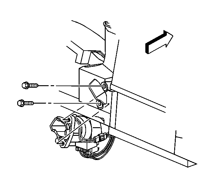
- Align the driver knee bolster bracket to the I/P. Install the bolts to the knee bolster at the instrument carrier in the sequence shown.
- Install the knee bolster bolts to the I/P lower trim panel.
- Install the 4 I/P driver knee bolster bracket screws.
- Position the filler panel for the steering column opening to the vehicle. Install the rear compartment release switch.
- Connect the electrical connector to the rear compartment release switch
- Align the filler panel to the I/P lower trim panel. Install the filler panel retainers to the I/P lower trim panel.
- Install the filler panel bolts.
- Position the left I/P insulator to the vehicle. Install the insulator to the stud at the accelerator pedal.
- Rotate the courtesy lamp clockwise in order to connect the courtesy lamp to the left I/P insulator.
- Install the left I/P insulator tabs to the lower I/P trim pad retainers.
- Enable the SIR system. Refer to Enabling the SIR System in SIR.
- Connect the battery ground cable. Refer to Battery Negative Cable Disconnection and Connection in Engine Electrical.
Notice: Use the correct fastener in the correct location. Replacement fasteners must be the correct part number for that application. Fasteners requiring replacement or fasteners requiring the use of thread locking compound or sealant are identified in the service procedure. Do not use paints, lubricants, or corrosion inhibitors on fasteners or fastener joint surfaces unless specified. These coatings affect fastener torque and joint clamping force and may damage the fastener. Use the correct tightening sequence and specifications when installing fasteners in order to avoid damage to parts and systems.
Tighten
Tighten the screws to 10 N·m (89 lb in).
Tighten
Tighten the screws to 2 N·m (18 lb in).

Tighten
| • | Tighten the horizontal screws to 2 N·m (18 lb in). |
| • | Tighten the vertical screws to 10 N·m (89 lb in). |


Tighten
Tighten the screws to 2 N·m (18 lb in).

Tighten
Tighten the screws to 2 N·m (18 lb in).


Tighten
Tighten the screws to 2 N·m (18 lb in).
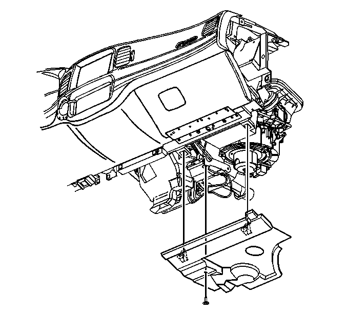

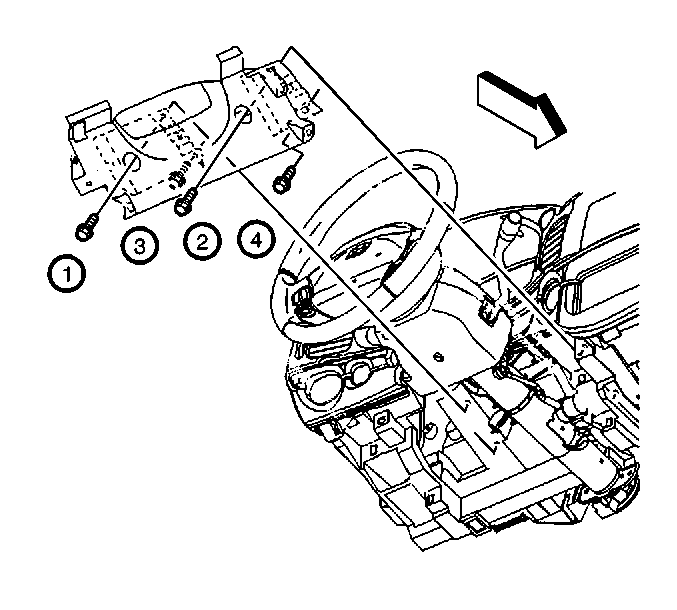
Tighten
Tighten the bolts to 10 N·m (89 lb in).
Tighten
Tighten the bolts to 2 N·m (18 lb in).
Tighten
Tighten the screws to 10 N·m (89 lb in).

Tighten
Tighten the bolts to 2 N·m (18 lb in).
Instrument Panel Lower Trim Panel Replacement Monte Carlo
Removal Procedure
- Disable the SIR system. Refer to Disabling the SIR System in SIR.
- Disconnect the battery ground cable. Refer to Battery Negative Cable Disconnection and Connection in Engine Electrical.
- Release the left instrument panel (I/P) insulator tabs from the lower I/P trim pad retainers.
- Rotate the courtesy lamp counterclockwise in order to disconnect the courtesy lamp from the left I/P insulator.
- Remove the left I/P insulator from the stud at the accelerator pedal.
- Remove the left I/P insulator.
- Remove the steering column filler panel. Refer to Steering Column Opening Filler Replacement .
- Remove the 4 knee bolster bracket screws.
- Remove the knee bolster bolts at the I/P lower trim panel.
- Remove the knee bolster bolts at the instrument carrier. Remove the knee bolster from the I/P.
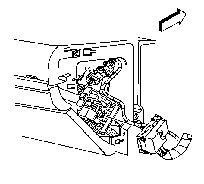
- Disconnect the SIR electrical connector to the right of the steering column.
- Remove the inflatable restraint steering wheel module. Refer to Inflatable Restraint Steering Wheel Module Replacement in SIR.
- Remove the steering wheel tilt lever. Refer to Tilt Lever Replacement - On Vehicle in Steering Wheel and Column.
- Remove the steering column covers. Refer to Steering Column Trim Covers Replacement - On Vehicle in Steering Wheel and Column.
- Remove the steering wheel. Refer to Steering Wheel Replacement in Steering Wheel and Column.
- Remove the I/P cluster trim plate screws.
- Starting at the right I/P cluster trip plate, grasp the trim plate and carefully pull rearward.
- Continue working around the I/P cluster trim plate until you have released all of the retainers from the I/P lower trim panel.
- Disconnect the electrical connectors from the hazard switch.
- Remove the I/P cluster trim plate.
- Remove the ignition cylinder bolts. Reposition the ignition cylinder.
- Remove the radio. Refer to Radio Replacement in Entertainment.
- Remove the HVAC control assembly. Refer to Heater and Air Conditioning Control Replacement in HVAC Systems-Manual.
- Disconnect the floor console storage bin lamp, if equipped.
- Remove the headlamp switch. Disconnect the headlamp switch electrical connector. Refer to Headlamp Switch Replacement in Lighting Systems.
- Disconnect the hood latch release handle. Push the hood release handle through the opening in the I/P.
- Remove the data link connector screws and disconnect the data link connector.
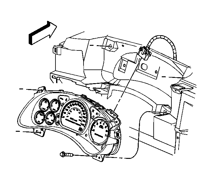
- Remove the I/P cluster. Refer to Instrument Cluster Replacement .
- Remove the garnish moldings from the left and the right windshield pillar. Refer to Windshield Pillar Garnish Molding Replacement in Interior Trim.
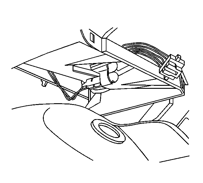
- Disconnect and reposition the left fuse block wiring harness.
- Starting at the right side, carefully lift upwards on the I/P upper trim panel in order to release the retainers. Continue working to your left until you have released all of the retainers.
- Disconnect the daytime running lamps sensor from the I/P upper trim panel.
- Remove the I/P upper trim panel.
- Remove the I/P compartment. Refer to Instrument Panel Compartment Replacement .
- Disconnect the I/P compartment lamp switch. Refer to Instrument Panel Compartment Lamp Replacement in Lighting Systems.
- Remove the right upper I/P trim plate. Refer to Instrument Panel Upper Trim Plate Replacement .
- Remove the right lower I/P trim plate. Refer to Instrument Panel Lower Trim Plate Replacement .
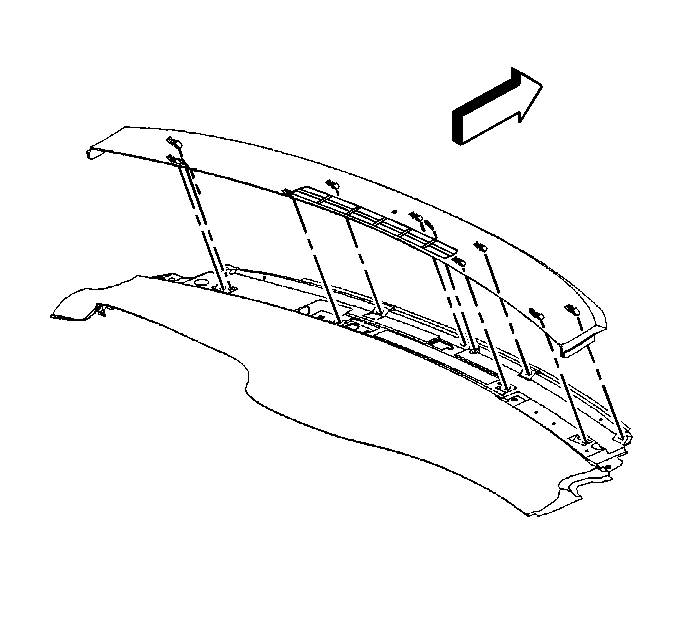
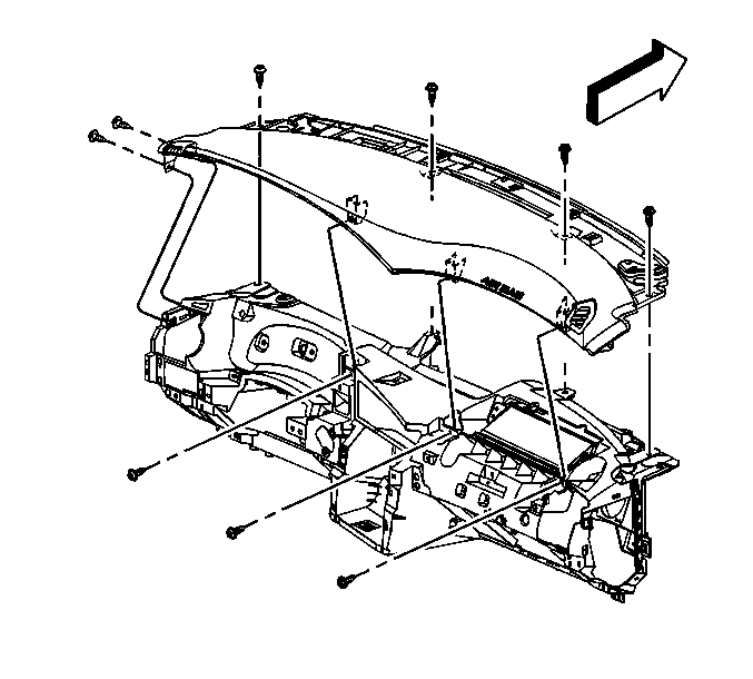
- Remove the I/P upper trim pad screws.
- Reach under the I/P upper trip pad and release the retainers from the remote keyless entry (RKE) module.
- Disconnect the electrical connector.
- Remove the RKE module.
- Remove the I/P upper trim pad. Refer to Instrument Panel Upper Trim Pad Replacement .
- Disconnect the inflatable restraint I/P module electrical connector.
- Remove the inflatable restraint I/P module. Refer to Inflatable Restraint Instrument Panel Module Replacement in SIR.
- Remove the right I/P insulator. Refer to Instrument Panel Insulator Panel Replacement - Right Side .
- Disconnect and reposition the right I/P fuse block wiring harness.
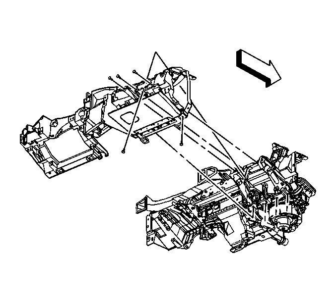
- Remove the small I/P lower trim panel screws.
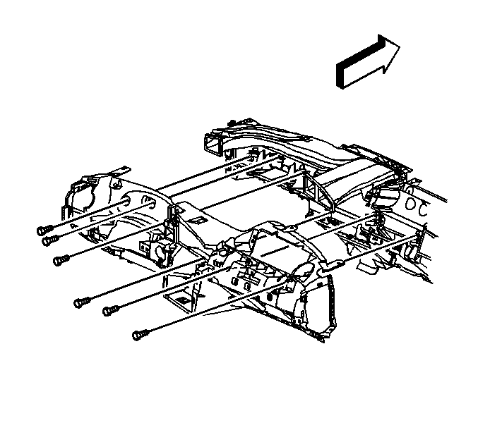
- Remove the large I/P lower trim panel screws.
- Reposition the I/P wiring harness.
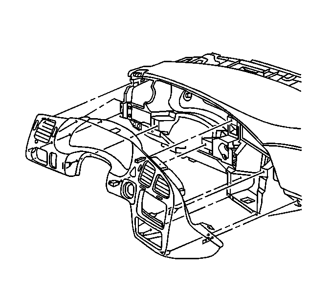
- Remove the I/P lower trim panel from the vehicle.
Caution: Refer to SIR Caution in the Preface section.
Caution: Refer to Battery Disconnect Caution in the Preface section.





Installation Procedure
- Position the I/P lower trim panel to the vehicle.
- Position the I/P wiring harness to the original location on the I/P assembly.
- Install the large I/P lower trim panel screws in the order shown in the graphic.
- Install the small I/P lower trim panel screws.
- Connect the right I/P fuse block wiring harness.
- Install the right I/P insulator. Refer to Instrument Panel Insulator Panel Replacement - Right Side .
- Install the inflatable restraint I/P module. Connect the electrical connector to the inflatable restraint I/P module. Refer to Inflatable Restraint Instrument Panel Module Replacement in SIR.
- Position the I/P upper trim pad to the upper I/P.
- Reach under the I/P upper trim pad and position the RKE wiring harness through the I/P upper trim pad opening. Install the RKE module. Connect the electrical connector to the RKE module.
- Install the I/P upper trim pad screws.
- Install the right lower I/P trim plate. Refer to Instrument Panel Lower Trim Plate Replacement .
- Install the right upper I/P trim plate. Refer to Instrument Panel Upper Trim Plate Replacement .
- Connect the I/P compartment lamp switch. Refer to Instrument Panel Compartment Lamp Replacement in Lighting Systems.
- Install the I/P compartment. Refer to Instrument Panel Compartment Replacement .
- Position the I/P upper trim panel to the vehicle. Connect the daytime running lamps (DRL) sensor to the I/P upper trim panel.
- Starting at the left side, install the trim panel retainers into the upper I/P. Continue working to your right until you have installed all of the retainers.
- Connect the left fuse block wiring harness.
- Install the garnish moldings to the right and to the left windshield pillar. Refer to Windshield Pillar Garnish Molding Replacement in Interior Trim.
- Install the I/P cluster. Refer to Instrument Cluster Replacement .
- Install the data link connector.
- Push the hood release handle through the opening in the I/P. Connect the hood latch release handle. Refer to Hood Primary Latch Release Cable Handle Replacement in Body Front End .
- Connect the headlamp switch electrical connector. Install the headlamp switch. Refer to Headlamp Switch Replacement in Lighting Systems.
- Connect the floor console storage bin lamp, if equipped.
- Install the HVAC control module. Refer to Heater and Air Conditioning Control Replacement in HVAC Systems-Manual.
- Install the radio. Refer to Radio Replacement in Entertainment.
- Position the ignition switch within the instrument panel.
- Install the ignition switch bolts.
- Position the I/P cluster trim plate to the I/P lower trim panel.
- Connect the electrical connector to the hazard switch.
- Carefully press the I/P cluster trim plate into the I/P lower trim panel. Fully engage all of the retainers.
- Install the I/P cluster trim plate screws.
- Install the steering wheel. Refer to Steering Wheel Replacement in Steering Wheel and Column.
- Install the steering column covers. Refer to Steering Column Trim Covers Replacement - On Vehicle in Steering Wheel and Column.
- Install the steering wheel tilt lever. Refer to Tilt Lever Replacement - On Vehicle in Steering Wheel and Column.
- Install the inflatable restraint steering wheel module. Refer to Inflatable Restraint Steering Wheel Module Replacement in SIR.
- Connect the SIR electrical connector to the right of the steering column.
- Align the knee bolster bracket to the I/P. Install the knee bolster bracket bolts at the I/P carrier in the sequence shown.
- Install the bolts that secure the driver I/P knee bolster to the I/P lower trim panel.
- Install the 4 knee bolster bracket screws.
- Install the steering column filler panel. Refer to Steering Column Opening Filler Replacement .
- Position the left I/P insulator to the vehicle. Install the left I/P insulator to the stud at the accelerator pedal.
- Rotate the courtesy lamp clockwise in order to connect the courtesy lamp to the left I/P insulator.
- Install the left I/P insulator tabs to the lower I/P trim pad retainers.
- Enable the SIR system. Refer to Enabling the SIR System in SIR.
- Connect the battery ground cable. Refer to Battery Negative Cable Disconnection and Connection in Engine Electrical.
Notice: Use the correct fastener in the correct location. Replacement fasteners must be the correct part number for that application. Fasteners requiring replacement or fasteners requiring the use of thread locking compound or sealant are identified in the service procedure. Do not use paints, lubricants, or corrosion inhibitors on fasteners or fastener joint surfaces unless specified. These coatings affect fastener torque and joint clamping force and may damage the fastener. Use the correct tightening sequence and specifications when installing fasteners in order to avoid damage to parts and systems.
Tighten
Tighten the screws to 10 N·m (89 lb in).

Tighten
Tighten the screws to 2 N·m (18 lb in).


Tighten
| • | Tighten the horizontal screws to 2 N·m (18 lb in). |
| • | Tighten the vertical screws to 10 N·m (89 lb in). |


Important: Do NOT pinch the DRL sensor wiring harness when you install the I/P upper trim panel.


Tighten
Tighten the data link connector screws to 2 N·m (18 lb in).

Tighten
Tighten the bolts to 10 N·m (89 lb in).

Tighten
Tighten the screws to 2 N·m (18 lb in).

Tighten
Tighten the bolts to 10 N·m (89 lb in).
Tighten
Tighten the bolts to 2 N·m (18 lb in).
Tighten
Tighten the screws to 10 N·m (89 lb in).


