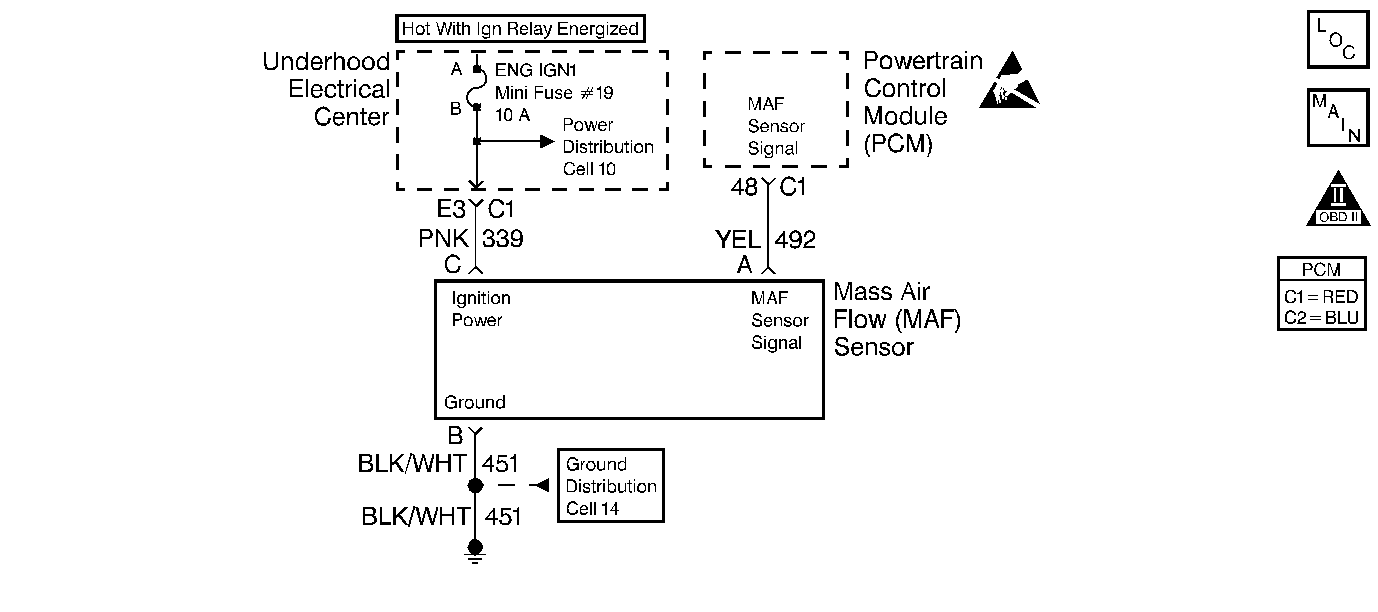
Circuit Description
The Mass Air Flow (MAF) sensor measures the amount of air ingested by the engine. The direct measurement of the air entering the engine is more accurate than calculating the airflow from the MAP, the IAT and the engine speed (speed/density). The MAF sensor has a battery feed, ground, and a signal circuit.
The MAF sensor used on this engine is a hot wire type. This engine uses the MAF sensor to measure air flow rate. The MAF output frequency is a function of the power required to keep the air flow sensing elements (hot wires) at a fixed temperature above the ambient temperature. Air flowing through the sensor cools the sensing elements. The amount of cooling is proportional to the amount of air flow. As the air flow increases, the MAF sensor requires a greater amount of current in order to maintain the hot wires at a constant temperature. The MAF sensor converts the changes in current draw to a frequency signal read by the PCM. The PCM calculates the air flow (grams per second) based on this signal.
The PCM monitors the MAF sensor frequency. The PCM can determine if the sensor is stuck low, stuck high, not providing the airflow value expected for a given operating condition, or that the signal appears to be stuck based on a lack of signal variation expected during the normal operation. This diagnostic checks for too low an airflow rate. When the PCM detects that the MAF sensor frequency is below a predetermined value, this DTC will set.
Conditions for Setting the DTC
| • | Engine running |
| • | Engine speed greater than 300 RPM |
| • | Ignition voltage greater than 8 volts |
| • | Mass Air Flow frequency less than 10 Hz |
| • | All conditions met for 1 second |
Action Taken When the DTC Sets
| • | The PCM illuminates the malfunction indicator lamp (MIL) when the diagnostic runs and fails. |
| • | The PCM utilizes speed density (RPM, MAP, IAT) for fuel management. |
| • | The PCM records the operating conditions at the time the diagnostic fails. The PCM stores this information in the Freeze Frame and/or the Failure Records. |
Conditions for Clearing the MIL/DTC
| • | The PCM turns OFF the malfunction indicator lamp (MIL) after 3 consecutive ignition cycles that the diagnostic runs and does not fail. |
| • | A last test failed, or current DTC, clears when the diagnostic runs and does not fail. |
| • | A history DTC clears after 40 consecutive warm-up cycles, if no failures are reported by this or any other emission related diagnostic. |
| • | Use a scan tool in order to clear the MIL and the DTC. |
Diagnostic Aids
If you can not find a problem with the ignition feed circuit to the component, inspect the circuit between the IGN 1 mini relay and the fuse for an open. Probe both sides of the ENG IGN1 fuse in order to determine if the IGN 1 mini relay is suppling power to the fuse. Refer to Ignition Relay Diagnosis for further diagnosis of the IGN 1 mini relay. Also inspect the IGN 1 fuse for being open.
If the ENG IGN1 fuse is open or the IGN mini relay is faulty, the following DTCs may set:
| • | P0102 |
| • | P0412 |
| • | P0418 |
| • | P0443 |
| • | P0740 |
| • | P1518 |
| • | P1860 |
The following may cause an intermittent:
| • | Mis-routed harness |
| • | Rubbed through wire insulation |
| • | Broken wire inside the insulation |
For an intermittent, refer to Symptoms .
Any un-metered air may cause this DTC to set. Check for the following:
| • | An engine vacuum leak |
| • | The PCV system for vacuum leaks |
| • | An incorrect PCV valve |
| • | The engine oil dip stick not fully seated |
| • | The engine oil fill cap loose or missing |
Test Description
The numbers below refer to the step numbers on the diagnostic table.
-
Monitoring the MAF sensor frequency will determine if the fault is present or the malfunction is intermittent. For any test that requires probing the PCM or component harness connectors, use the Connector Test Adapter Kit J 35616 . Using this kit will prevent any damage to the harness connector terminals.
-
Using the Freeze Frame and/or Failure Records data may aid in locating an intermittent condition. If you cannot duplicate the DTC, the information included in the Freeze Frame and/or Failure Records data can help determine how many miles since the DTC set. The Fail Counter and Pass Counter can also help determine how many ignition cycles the diagnostic reported a pass and/or a fail. Operate the vehicle within the same freeze frame conditions (RPM, load, vehicle speed, temperature etc.) that you observed. This will isolate when the DTC failed. For any test that requires probing the PCM or component harness connectors, use the Connector Test Adapter Kit J 35616 . Using this kit prevents any damage to the harness connector terminals.
-
This step checks whether the MAF sensor signal circuit is open or shorted to a ground. If 5.0 volts is present the circuit is OK.
-
This step checks whether the B+ supply and the ground circuit are OK.
-
This step checks whether B+ is available at the MAF sensor.
-
Inspect the fuse 19 for being open. If the fuse is open, inspect the MAF sensor ignition feed circuit for a short to ground. If no voltage is on the ignition feed circuit to the MAF sensor, inspect the ignition relay for proper operation. Probe both sides of the ENG IGN1 fuse in order to determine if the ignition relay is suppling the voltage. Refer to Body and Accessories for further diagnosis of the ignition relay. When a malfunction occurs with the ignition relay or the ignition feed circuit, multiple DTCs will set. The following DTCs may set: P0102, P0412, P0418, P0443, P0740, P1518, P1860.
-
Inspect for proper terminal tension/connections at the PCM harness before replacing the PCM.
Step | Action | Value(s) | Yes | No | ||||||||
|---|---|---|---|---|---|---|---|---|---|---|---|---|
1 | Did you perform the Powertrain On-Board Diagnostic (OBD) System Check? | -- | ||||||||||
Is the MAF sensor frequency below the specified value? | 10 Hz | |||||||||||
Does the scan tool indicate that this diagnostic failed this ignition? | -- | Go to Diagnostic Aids | ||||||||||
Is the voltage near the specified value? | 5.0V | |||||||||||
Connect a test lamp J 35616-200 between the MAF sensor ignition feed circuit and the ground circuit at the MAF sensor harness connector. Is the test lamp illuminated? | -- | |||||||||||
Connect a test lamp J 35616-200 between the MAF sensor ignition feed circuit and the battery ground. Is the test lamp illuminated? | -- | |||||||||||
7 |
Did you find a poor connection? | -- | ||||||||||
8 |
Did you find the MAF sensor signal circuit open or shorted? | -- | ||||||||||
9 | Locate and repair the open in the ground circuit to the MAF sensor. Refer to Body and Accessories/Wiring Systems. Is the action complete? | -- | -- | |||||||||
Repair the ignition feed circuit to the MAF sensor. Refer to Body and Accessories/Wiring Systems. Is the action complete? | -- | -- | ||||||||||
11 | Replace the MAF sensor. Refer to Mass Airflow Sensor Replacement . Is the action complete? | -- | -- | |||||||||
12 |
Important:: Program the replacement PCM. Refer to Powertrain Control Module/Throttle Actuator Control Module Replacement . Replace the PCM. Is the action complete? | -- | -- | |||||||||
13 |
Does the scan tool indicate that this test ran and passed? | -- | ||||||||||
14 | Select the Capture Info option and the Review Info option using the scan tool. Does the scan tool display any DTCs that you have not diagnosed? | -- | Go to the applicable DTC table | System OK |
