Tools Required
| • | J 39765 Fuel Sender
Lock Nut Wrench |
Removal Procedure
- Remove the fuel tank. Refer to
Fuel Tank Replacement
.
Notice: Clean all of the following areas before performing any disconnections
in order to avoid possible contamination in the system:
| • | The fuel pipe connections |
| • | The areas surrounding the connections |

- Refer to
Plastic Collar Quick Connect Fitting Service
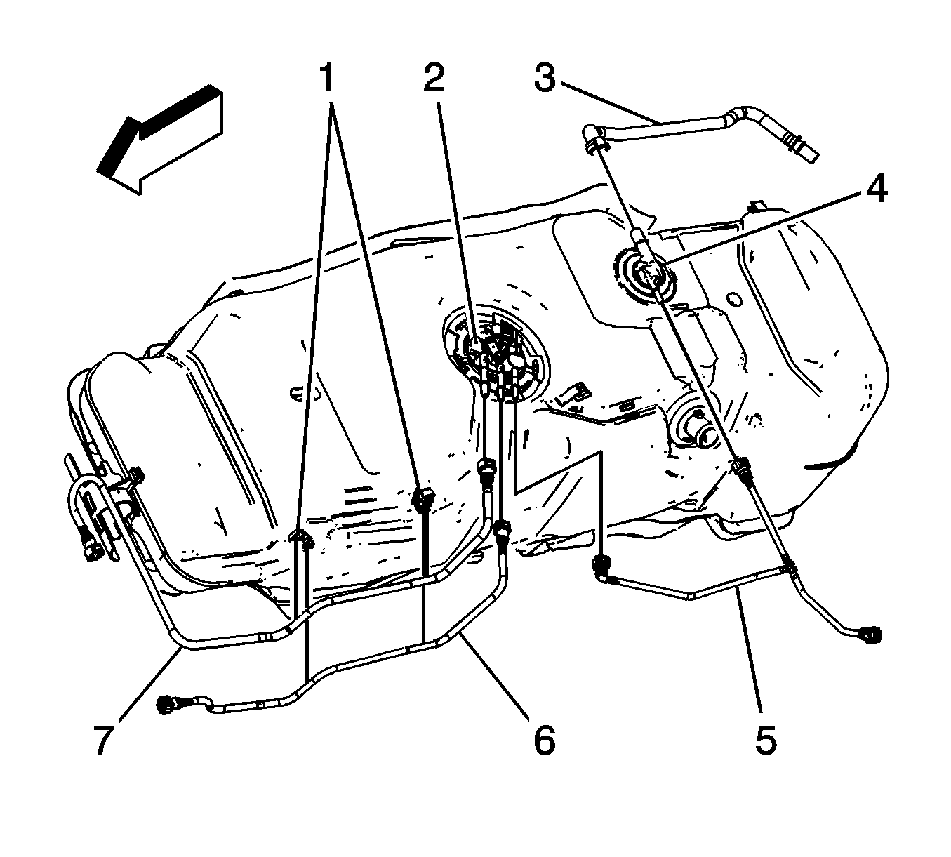
in order to disconnect the following from the fuel tank module (2):
| • | The evaporative emission (EVAP) pipe (5) |
| • | The fuel return pipe (6) |

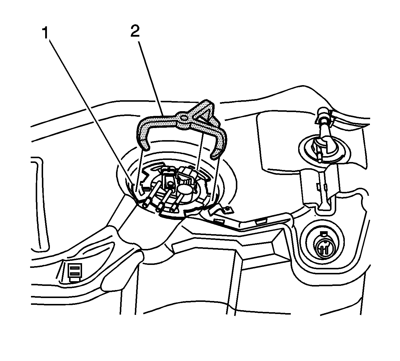
Important: Do not allow the tool (2) to come
in contact with the male pipe ends while unlocking the cam lock ring (1).
- Rotate the cam lock ring (1) counter-clockwise using the J 39765
or J39765-A
(2).
- Remove the cam lock ring (1) from the fuel tank.

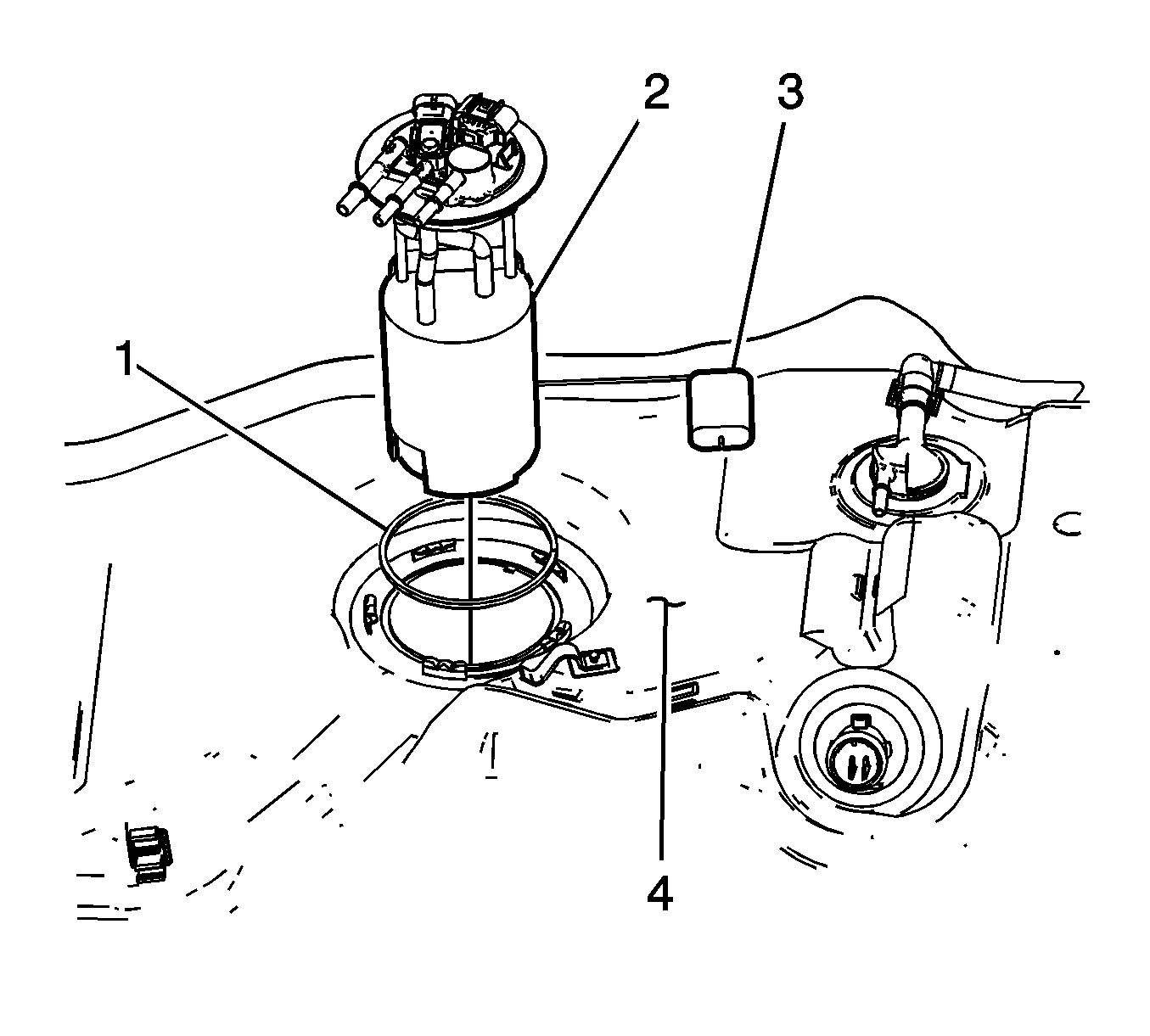
- Complete the following in order to remove the fuel tank module (2) from
the fuel tank (4):
| 5.1. | Raise the module (2) upward from the fuel tank (4). |
| 5.2. | Tilt the module (2), to allow the fuel level sensor arm and float (3)
to clear the fuel tank module opening. |
- Remove the fuel tank module seal (1).
Do not reuse
the seal (1).
Caution: Drain the fuel from the fuel sender assembly into an approved container
in order to reduce the risk of fire and personal injury. Never store the fuel
in an open container.
- Clean the fuel module sealing surfaces.
Installation Procedure
- Clean any contamination from the male pipe ends of the fuel tank module.
Caution: In order to reduce the risk of fire and personal injury that may result
from a fuel leak, always replace the fuel sender gasket when reinstalling
the fuel sender assembly.

- Place the new fuel tank module seal (1) on the fuel tank.
- Complete the following in order to install the fuel tank module (2)
into the fuel tank (4):
| 3.1. | Insert the module (2) into the fuel tank allowing the fuel level
sensor arm and float (3) to clear module opening. |
| 3.2. | Lower the module (2) downward into the fuel tank (4). |

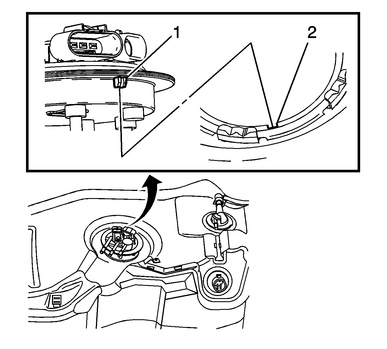
- Press the fuel tank module downward, aligning the tang (1)
with the notch (2) in the fuel tank.
- Position the cam lock ring to the fuel tank

Important: Do not allow the tool (2) to come
in contact with the male pipe ends while locking the cam lock ring (1).
- Rotate the cam lock ring (1) clockwise using the J 39765
or J39765-A
(2) until fully seated.

- Refer to
Plastic Collar Quick Connect Fitting Service
in order to connect the following to the fuel tank module (2):
| • | The evaporative emission (EVAP) pipe (5) |
| • | The fuel return pipe (6) |
- Install the fuel tank. Refer to
Fuel Tank Replacement
.


