Fuel Tank Replacement Pickup with Type 2 Tank
Tools Required
| • | J 45529 Tank Removal Tool |
| • | J 45878 Combustible Gas Detector |
Removal Procedure
- If the tank is being removed in order to replace the high pressure lock-off (HPL) solenoid or for internal tank cleaning perform the High Pressure Lock-Off Solenoid Replacement instead of this procedure.
- Relieve the CNG fuel system pressure. Refer to Fuel Pressure Relief .
- If the tank is to be discarded or shipped it must be vented. Venting will damage the high pressure lock-off (HPL) solenoid. Refer to Fuel Tank Venting .
- Disconnect the negative battery cable. Refer to Battery Negative Cable Disconnection and Connection in Engine Electrical in the C/K Pickup service manual.
- Remove the fuel tank cover. Refer to Fuel Tank Cover Replacement .
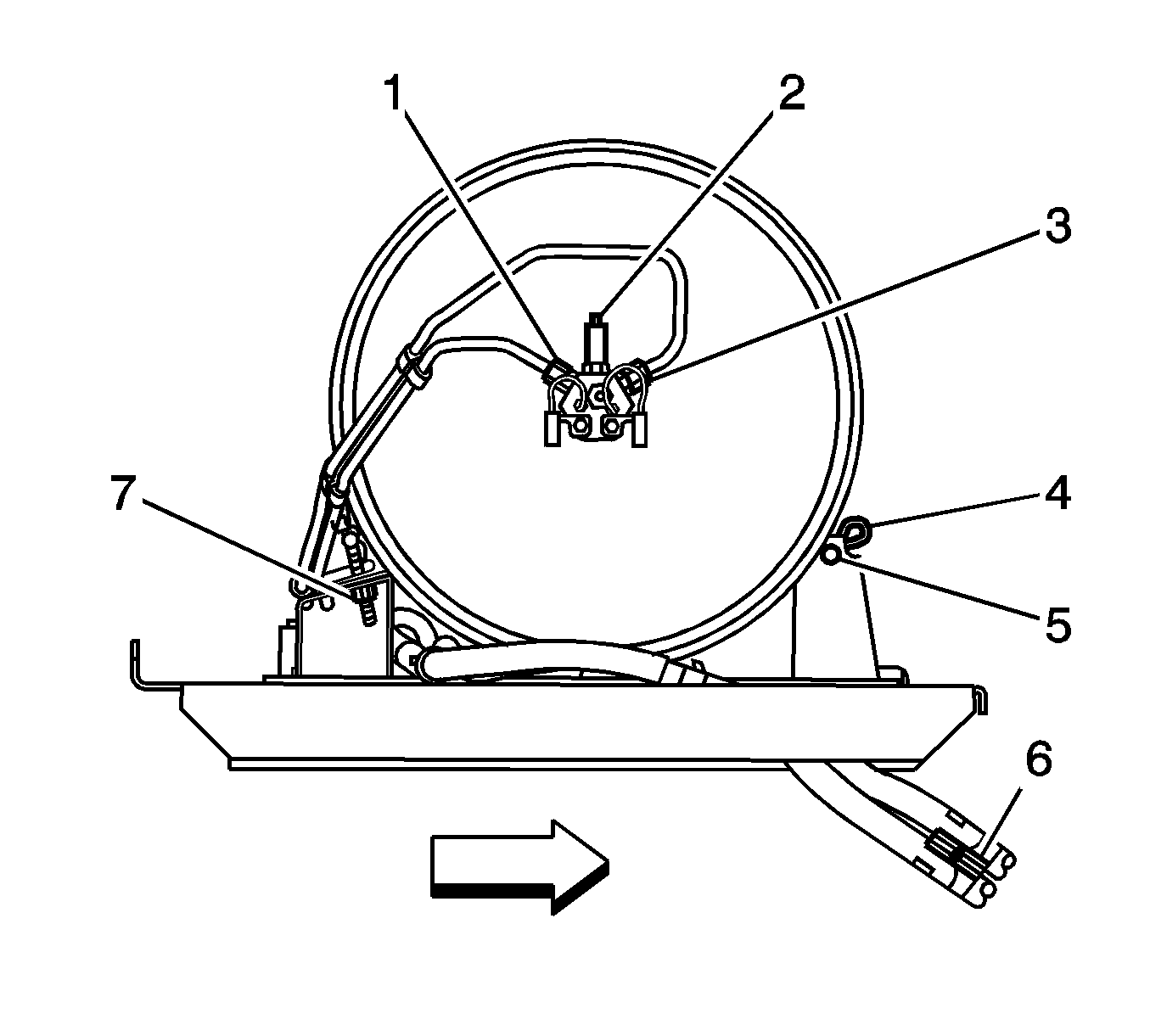
- Disconnect the high pressure lock-off (HPL) solenoid connectors (5,7).
- Disconnect the fuel tank pressure (FTP) sensor connector (1).
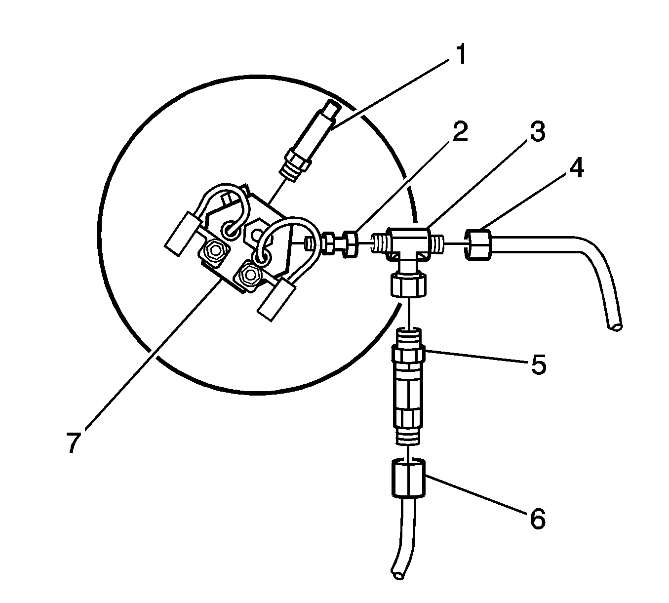
- Disconnect the high pressure regulator (HPR) fuel inlet line (3).
- Remove the HPR fuel inlet fitting (6). Capture the filter spring (4), filter (3) and seal (2) that are located behind the inlet fitting.
- Remove the HPR mounting nut (1).
- Disconnect the fuel line (4) from the tee fitting (3).
- Disconnect the tee fitting (3) from the HPL fitting (2).
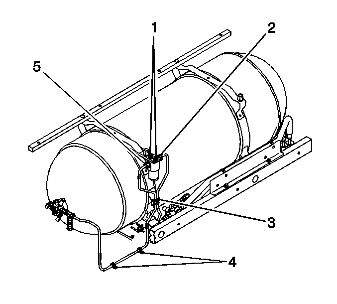
- Disconnect the fuel line clips (4) at the lower tank cover mounting bracket.
- Disconnect the fuel line clips (3) at the tank frame (3).
- Remove the fuel filter mounting bolts (1).
- Remove the fuel filter and line assembly from the vehicle.
- Disconnect the HPR coolant hoses from the lower tank cover mounting bracket retainers.
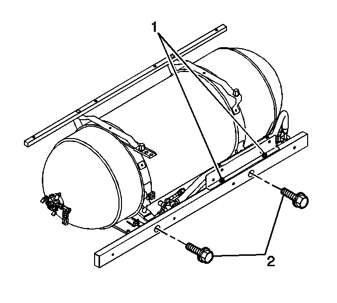
- Remove the lower tank cover mounting bracket bolts (2).
- Set aside the mounting bracket assembly in order to gain access to the tank strap retaining nuts.
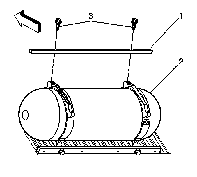
- Remove the upper tank cover mounting bracket bolts (3).
- Remove the upper tank cover mounting bracket (1).
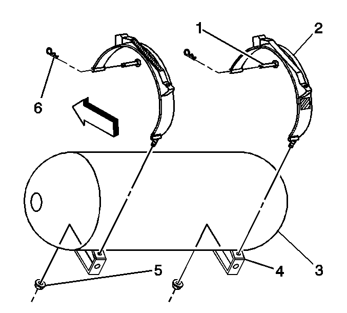
- Remove the tank strap retaining nuts (5).
- Remove the tank strap upper mounting clips (6) and pins (1).
- Remove the tank straps from the vehicle.
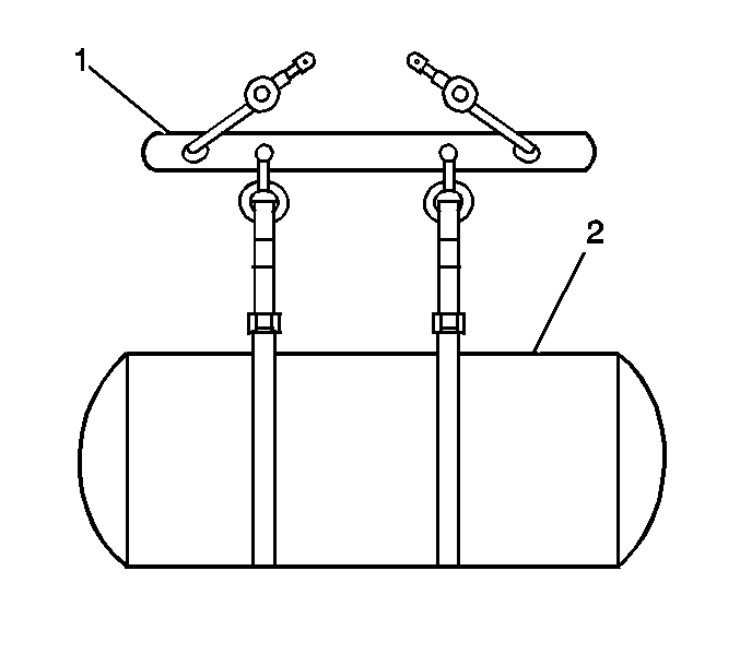
- Place the J 45529 (1) around the tank (2).
- Connect the J 45529 (1) to a suitable lifting device and remove the tank from the vehicle.
Caution: Unless directed otherwise, the ignition and start switch must be in the OFF or LOCK position, and all electrical loads must be OFF before servicing any electrical component. Disconnect the negative battery cable to prevent an electrical spark should a tool or equipment come in contact with an exposed electrical terminal. Failure to follow these precautions may result in personal injury and/or damage to the vehicle or its components.
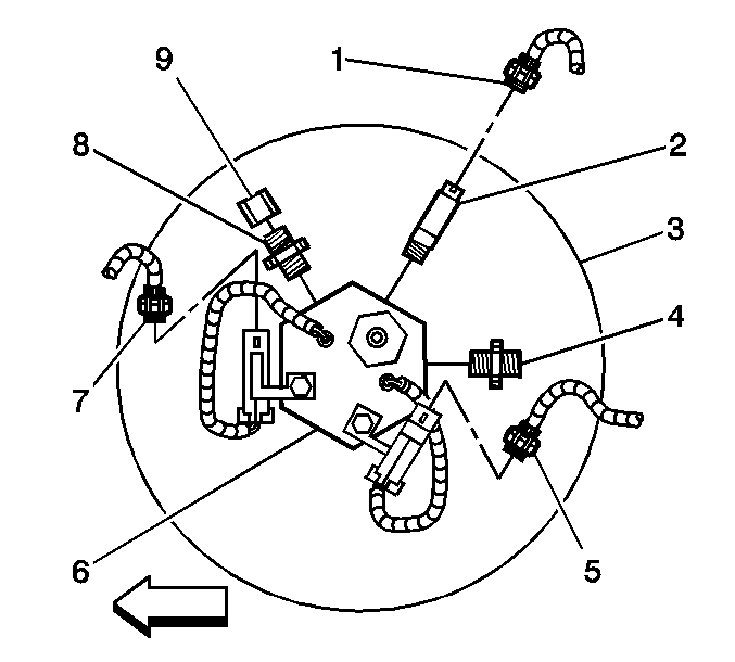
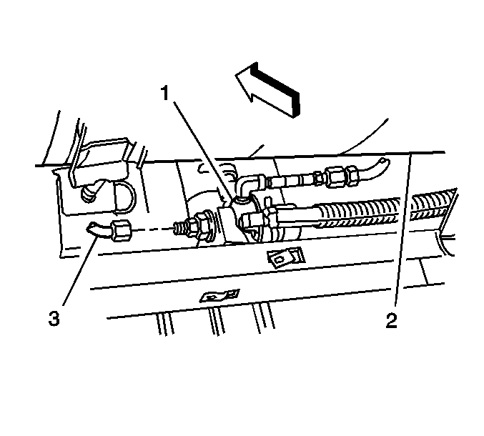
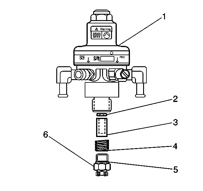
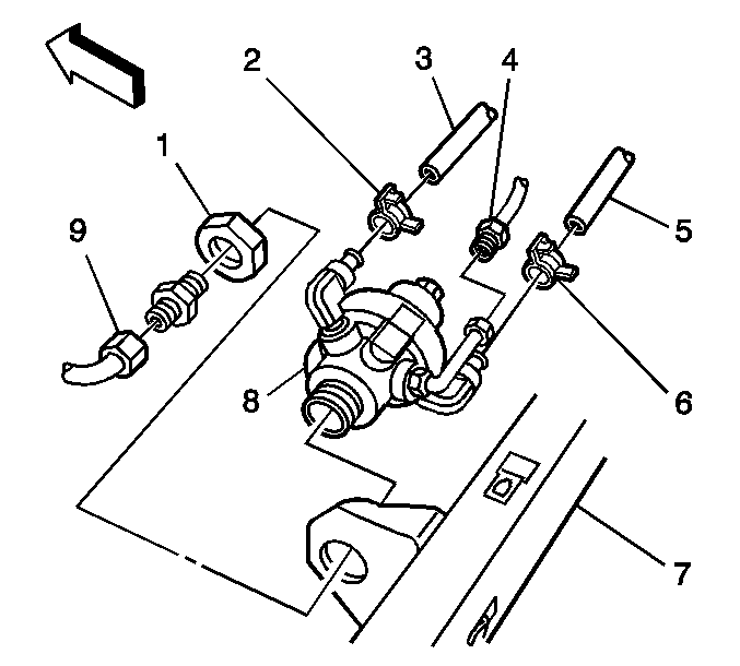
Important: Do not hold the HPR using the HPR cover hex flange. As required wedge a wrench between the HPR and the tank frame in order to keep the HPR from spinning in the bracket.
Installation Procedure
- Lower the fuel tank (2) into the tank mounting frame ensuring that the high pressure lock-off solenoid is properly oriented to the fuel line.
- Place the straps (2) around the tank.
- Install the tank strap upper mounting pins (1) and clips (6).
- Install the tank strap mounting nuts (5).
- Install the upper tank cover mounting bracket (1) and bolts.
- Slide the lower tank cover mounting bracket over the HPR and into position.
- Install the lower tank cover mounting bracket and bolts (2).
- Attach the HPR coolant hoses to the lower tank cover mounting bracket retainers.
- Install the HPR mounting nut (1).
- Install the filter spring (4), filter (3) and seal (2) into the HPR inlet port.
- Install the HPR fuel inlet line fitting (6) with a new O-ring. Lubricate the O-ring with petroleum jelly.
- Install the fuel filter and line assembly.
- Fasten the fuel line at the lower tank cover mounting bracket (4) and the tank strap (3).
- Connect the fuel line (3) to the HPR fuel inlet fitting with a new O-ring face seal. Lubricate the O-ring face seal with petroleum jelly.
- Connect the tee (3) to the HPL fitting (2) with a new O-ring face seal. Lubricate the O-ring with petroleum jelly.
- Connect the fuel line (4) to the HPL fitting (3) with a new O-ring face seal. Lubricate the O-ring face seal with petroleum jelly.
- Connect the HPL solenoid connectors (5, 7).
- Connect the FTP sensor connector (1).
- Connect the negative battery cable. Refer to Battery Negative Cable Disconnection and Connection in Engine Electrical in the C/K Pickup service manual.
- Fill the CNG fuel system.
- Start the engine and use the J 45878 in order to inspect for CNG fuel system leaks at each serviced fitting.
- Install the fuel tank cover. Refer to Fuel Tank Cover Replacement .


Notice: Use the correct fastener in the correct location. Replacement fasteners must be the correct part number for that application. Fasteners requiring replacement or fasteners requiring the use of thread locking compound or sealant are identified in the service procedure. Do not use paints, lubricants, or corrosion inhibitors on fasteners or fastener joint surfaces unless specified. These coatings affect fastener torque and joint clamping force and may damage the fastener. Use the correct tightening sequence and specifications when installing fasteners in order to avoid damage to parts and systems.
Tighten
Tighten the tank strap mounting bolts to 47 N·m (35 lb ft).

Tighten
Tighten the bolts to 8 N·m (71 lb in).

Tighten
Tighten the bolts to 50 N·m (37 lb ft).

Important: Do not hold the HPR using the HPR cover hex flange. As required wedge a wrench between the HPR and the tank frame in order to keep the HPR from spinning in the bracket.
Tighten
Tighten the nut to 54 N·m (40 lb ft).

Caution: Natural gas is stored under high pressure. If a leak occurs, the high pressure could cause a personal injury. In order to prevent Compressed Natural Gas (CNG) fuel leaks, always replace the CNG fuel system O-rings during service.
Tighten
Tighten the fuel line fitting to 48 N·m (35 lb ft).

Tighten
Tighten the bolts (1) to 27 N·m (20 lb ft).

Tighten
Tighten the fitting to 37 N·m (27 lb ft).

Tighten
Tighten the fitting to 37 N·m (27 lb ft).
Tighten
Tighten the fitting to 37 N·m (27 lb ft).

Fuel Tank Replacement Cab/Chassis with Type 2 Tank
Tools Required
| • | J 45529 Tank Removal Tool |
| • | J 45878 Combustible Gas Detector |
Removal Procedure
- If the tank is being removed in order to replace the high pressure lock-off (HPL) solenoid or for internal tank cleaning perform the High Pressure Lock-Off Solenoid Replacement instead of this procedure.
- Relieve the CNG fuel system pressure. Refer to Fuel Pressure Relief .
- If the tank is to be discarded or shipped it must be vented. Venting will damage the high pressure lock-off (HPL) solenoid. Refer to Fuel Tank Venting .
- Disconnect the negative battery cable. Refer to Battery Negative Cable Disconnection and Connection in Engine Electrical in the C/K Pickup service manual.
- Remove the truck body as required on ZW9 equipped vehicles in order to gain access to the CNG fuel tank.
- Disconnect the high pressure lock-off (HPL) solenoid connectors (5,7).
- Disconnect the fuel tank pressure (FTP) sensor connector (1).
- Disconnect the HPL fuel lines (1,3).
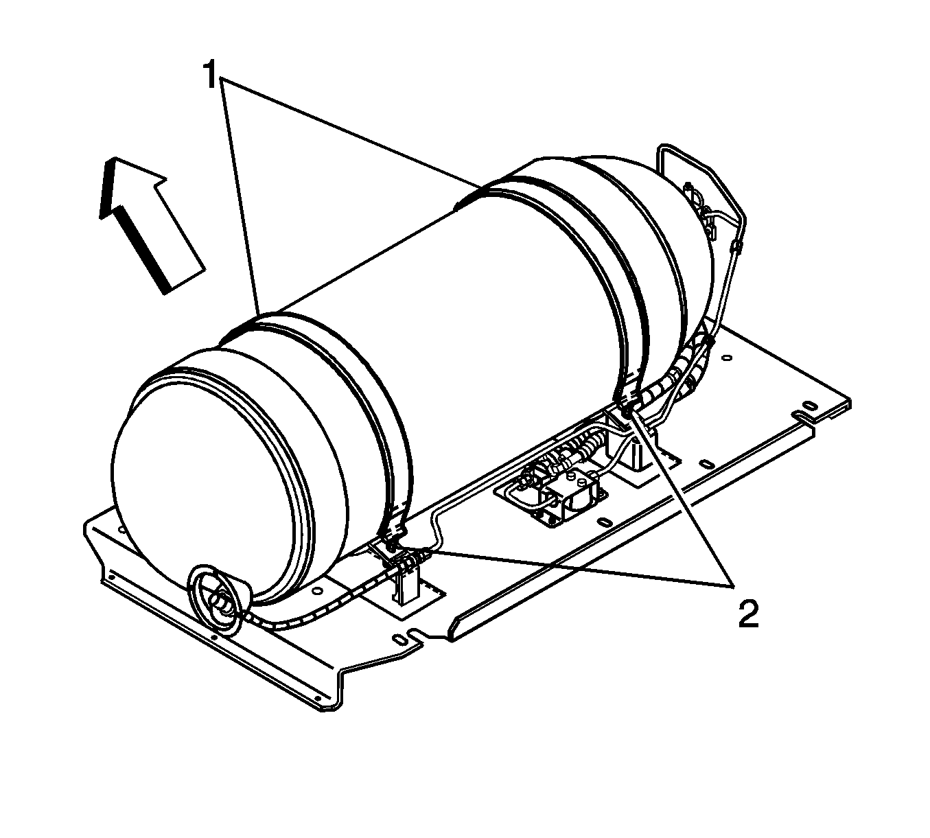
- Remove the tank strap retaining nuts (2).
- Remove the clips (4) and pins (5) from the tank strap mounting bracket.
- Remove the tank straps (1).
- Place the J 45529 (1) around the tank (2).
- Connect the J 45529 (1) to a suitable lifting device and remove the tank from the vehicle.
Caution: Natural gas is highly flammable. In order to reduce the risk of fire and personal injury, keep sparks, flames, and smoking materials away from the vehicle while you perform the Compressed Natural Gas (CNG) fuel system service.
Caution: The Compressed Natural Gas (CNG) system operates at pressures up to 24820 kpa (3600 psi). Relieve the CNG fuel system pressure before servicing CNG fuel system components in order to reduce the risk of fire and personal injury.
Caution: Unless directed otherwise, the ignition and start switch must be in the OFF or LOCK position, and all electrical loads must be OFF before servicing any electrical component. Disconnect the negative battery cable to prevent an electrical spark should a tool or equipment come in contact with an exposed electrical terminal. Failure to follow these precautions may result in personal injury and/or damage to the vehicle or its components.



Installation Procedure
- Lower the fuel tank (2) into the tank mounting frame with the J 45529 .
- Place the straps (1) around the tank.
- Ensure that the high pressure lock-off solenoid is properly oriented to the fuel line fittings.
- Install the tank strap mounting pins (5) and clips (4).
- Install the tank strap mounting nuts (7).
- Connect the fuel lines (1,3) to the HPL fittings with new O-ring face seals. Lubricate the O-ring face seals with petroleum jelly.
- Connect the HPL solenoid connectors (5, 7).
- Connect the FTP sensor connector (1).
- Connect the negative battery cable. Refer to Battery Negative Cable Disconnection and Connection in Engine Electrical in the C/K Pickup service manual.
- Fill the CNG fuel system.
- Start the engine and use the J 45878 in order to inspect for CNG fuel system leaks at each serviced fitting.
- Install the truck body as required on ZW9 equipped vehicles.


Notice: Use the correct fastener in the correct location. Replacement fasteners must be the correct part number for that application. Fasteners requiring replacement or fasteners requiring the use of thread locking compound or sealant are identified in the service procedure. Do not use paints, lubricants, or corrosion inhibitors on fasteners or fastener joint surfaces unless specified. These coatings affect fastener torque and joint clamping force and may damage the fastener. Use the correct tightening sequence and specifications when installing fasteners in order to avoid damage to parts and systems.
Tighten
Tighten the tank strap mounting bolts to 47 N·m (35 lb ft).
Caution: Natural gas is stored under high pressure. If a leak occurs, the high pressure could cause a personal injury. In order to prevent Compressed Natural Gas (CNG) fuel leaks, always replace the CNG fuel system O-rings during service.
Tighten
Tighten the lines to 37 N·m (27 lb ft).

Fuel Tank Replacement Pickup with Type 4 Tank
Tools Required
J 45529 Tank Removal Tool
Removal Procedure
- Perform the High Pressure Lock-Off Solenoid Replacement instead of this procedure if the tank is being removed for any of the following reasons:
- If the tank is being removed in order to perform non-CNG related repair to the vehicle, the tank may not require venting. However, the following must be observed:
- Relieve the CNG fuel system line pressure. Refer to Fuel Pressure Relief .
- Disconnect the negative battery cable. Refer to Battery Negative Cable Disconnection and Connection in Engine Electrical in the C/K Pickup service manual.
- Remove the fuel tank cover. Refer to Fuel Tank Cover Replacement .
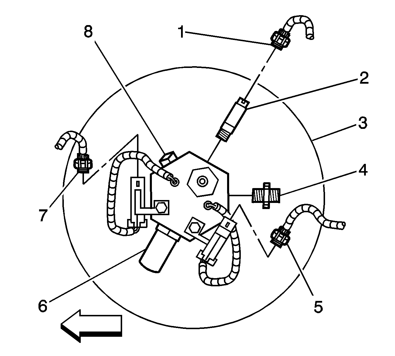
- Disconnect the HPL solenoid connectors (5, 7).
- Disconnect the fuel tank pressure (FTP) sensor connector (1).
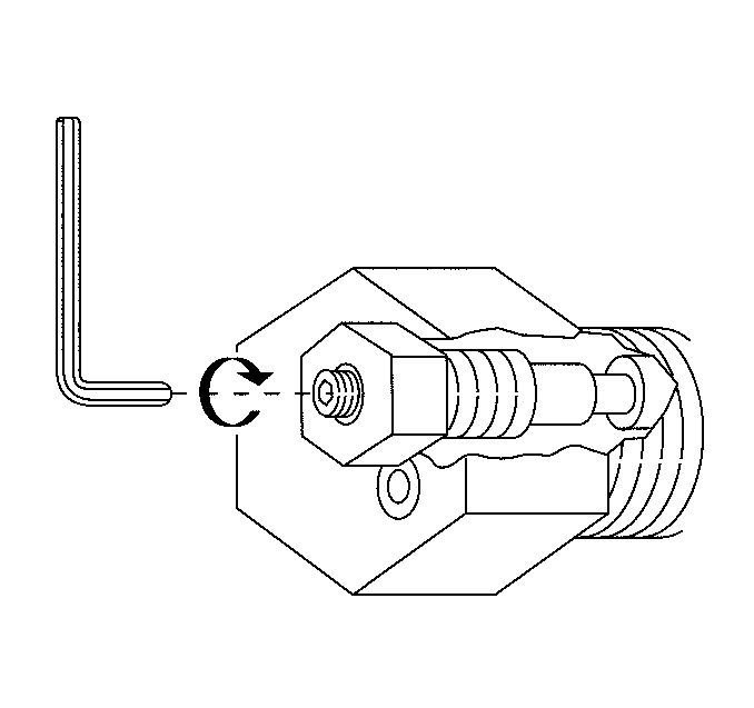
- Close the HPL manual lock-down screw.
- Disconnect the high pressure regulator (HPR) fuel inlet line (3).
- Remove the HPR fuel inlet fitting (6). Capture the filter spring (4), filter (3) and seal (2) that are located behind the inlet fitting.
- Remove the HPR mounting nut (1).
- Disconnect the HPR coolant hoses from the lower tank cover mounting bracket retainers.
- Disconnect all fuel line mounting clips as necessary.
- Remove the lower tank cover mounting bracket bolts (2).
- Set aside the mounting bracket assembly.
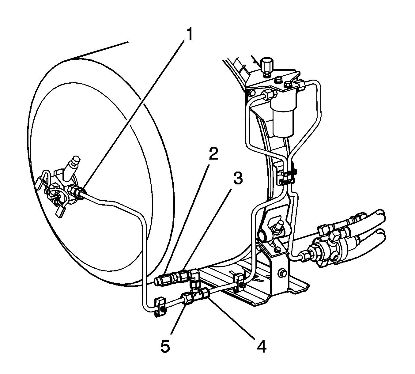
- Disconnect the fuel line (4) from the tee fitting (5).
- Disconnect the fuel line (1) from the HPL.
- Disconnect the fuel inlet line (2) from the check valve.
- Remove the fuel line and check valve assembly from the vehicle.
- Disconnect the fuel line clips (3) at the tank frame (3).
- Remove the fuel filter mounting bolts (1).
- Remove the fuel filter and line assembly from the vehicle.
- Remove the upper tank cover mounting bracket bolts (3).
- Remove the upper tank cover mounting bracket (1).
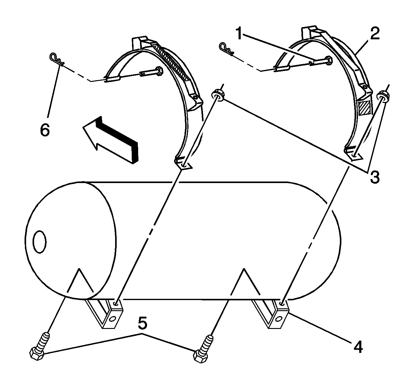
- Remove the tank strap retaining nuts (3).
- Remove the tank strap upper mounting clips (6) and pins (1).
- Remove the tank straps from the vehicle.
- Place the J 45529 (1) around the tank (2).
- Connect the J 45529 (1) to a suitable lifting device and remove the tank from the vehicle.
| • | High pressure lock-off (HPL) solenoid replacement |
| • | Type 4 fuel tank pressure relief device (PRD) replacement |
| • | CNG fuel tank replacement |
| • | Internal cleaning of the compressed natural gas (CNG) fuel tank |
| • | Transportation of a pressurized CNG fuel tank is prohibited by law. The CNG fuel tank must be vented prior to consignment. Venting will damage the HPL solenoid. Refer to Fuel Tank Venting . |
| • | Storing a pressurized CNG fuel tank outside of the vehicle may be prohibited. Contact the authority having jurisdiction prior to storing a pressurized CNG fuel tank. |
| • | Operate the vehicle on CNG until the fuel tank pressure has dropped below 3 447 kPa (500 psi) in order to ensure accurate tank strap tightening. |
| • | The pressurized CNG fuel tank must be properly restrained outside of the vehicle and protected from unauthorized access. Restrain the fuel tank to a shipping pallet or with the CNG fuel tank brackets from the vehicle and move to a secure area. |
| • | Attach a tag or label to the HPL solenoid indicating that the CNG fuel tank is pressurized. |
| • | Protect the tank from ultra-violet (UV) radiation and physical damage while removed from the vehicle. |
| • | Inspect any CNG fuel tank that has been removed from the vehicle for damage prior to installation. Refer to Fuel Tank Inspection . |
Caution: Unless directed otherwise, the ignition and start switch must be in the OFF or LOCK position, and all electrical loads must be OFF before servicing any electrical component. Disconnect the negative battery cable to prevent an electrical spark should a tool or equipment come in contact with an exposed electrical terminal. Failure to follow these precautions may result in personal injury and/or damage to the vehicle or its components.


Important: Do not hold the HPR using the HPR cover hex flange. As required wedge a wrench between the HPR and the tank frame in order to keep the HPR from spinning in the bracket.




Installation Procedure
- Install new tank strap isolators to the upper and lower fuel tank mounting straps.
- Lower the fuel tank (2) onto the tank mounting frame ensuring that the HPL solenoid is properly oriented to the fuel line.
- Place the straps (2) around the tank.
- Install the tank strap upper mounting pins (1) and clips (6).
- Install the tank strap mounting nuts (3) to the tee bolts (5).
- Install the upper tank cover mounting bracket (1) and bolts.
- Slide the lower tank cover mounting bracket over the HPR and into position.
- Install the lower tank cover mounting bracket and bolts (2).
- Attach the HPR coolant hoses to the lower tank cover mounting bracket retainers.
- Install the HPR mounting nut (1).
- Install the filter spring (4), filter (3) and seal (2) into the HPR inlet port.
- Install the HPR fuel inlet line fitting (6) with a new O-ring. Lubricate the O-ring with petroleum jelly.
- Install the fuel filter and line assembly.
- Fasten the fuel line at the lower tank cover mounting bracket (4) and the tank strap (3).
- Connect the fuel line (3) to the HPR fuel inlet fitting with a new O-ring face seal. Lubricate the O-ring face seal with petroleum jelly.
- Connect the filter fuel line (4) to the fuel line check valve assembly with a new O-ring face seal. Lubricate the O-ring with petroleum jelly.
- Connect the fuel line check valve assembly (1) to the HPL fitting with a new O-ring face seal. Lubricate the O-ring face seal with petroleum jelly.
- Connect the fuel inlet line (2) to the fuel line check valve assembly (3).
- Connect the HPL solenoid connectors (5, 7).
- Connect the FTP sensor connector (1).
- Connect the negative battery cable. Refer to Battery Negative Cable Disconnection and Connection in Engine Electrical in the C/K Pickup service manual.
- Open the HPL manual lock-down screw.
- Fill the CNG fuel tank.
- Start the engine on CNG and inspect for CNG fuel system leaks at each serviced fitting.
- Install the fuel tank cover. Refer to Fuel Tank Cover Replacement .
Important: A Type 4 fuel tank will expand and contract as the internal pressure increases and decreases. In order to compensate for expansion and contraction the tank strap rubber isolator is designed to deform slightly. Always install new isolators in order to achieve accurate tank strap torque. Accurate tank strap torque can only be achieved at tank pressures below 3 447 kPa (500 psi).


Notice: Use the correct fastener in the correct location. Replacement fasteners must be the correct part number for that application. Fasteners requiring replacement or fasteners requiring the use of thread locking compound or sealant are identified in the service procedure. Do not use paints, lubricants, or corrosion inhibitors on fasteners or fastener joint surfaces unless specified. These coatings affect fastener torque and joint clamping force and may damage the fastener. Use the correct tightening sequence and specifications when installing fasteners in order to avoid damage to parts and systems.
Tighten
Tighten the tank strap mounting nuts to 47 N·m (35 lb ft).

Tighten
Tighten the bolts to 8 N·m (71 lb in).

Tighten
Tighten the bolts to 50 N·m (37 lb ft).

Important: Do not hold the HPR using the HPR cover hex flange. As required wedge a wrench between the HPR and the tank frame in order to keep the HPR from spinning in the bracket.
Tighten
Tighten the nut to 54 N·m (40 lb ft).

Caution: Natural gas is stored under high pressure. If a leak occurs, the high pressure could cause a personal injury. In order to prevent Compressed Natural Gas (CNG) fuel leaks, always replace the CNG fuel system O-rings during service.
Tighten
Tighten the fuel line fitting to 48 N·m (35 lb ft).

Tighten
Tighten the bolts (1) to 27 N·m (20 lb ft).

Tighten
Tighten the fitting to 37 N·m (27 lb ft).

Tighten
Tighten all the fuel line fittings to 37 N·m (27 lb ft).

Important: Bubbles can be observed on the tank surface for up to 4 hours after re-pressurization of an empty tank. The bubbles are caused by air trapped between the liner and the composite fiber wrap. This condition is referred to as Trapped Air Migration and does not indicate gas leakage. Inspect for leakage with a liquid leak detector such as Snoop® or equivalent. Always rinse the liquid leak detector from the tank and fittings with clean water after inspection. The electronic combustible gas detector J 45878 is not recommended for leak detection on or near the Type 4 CNG fuel tank for several hours after re-pressurization. The detector can falsely indicate a leak as the trapped air is expelled.
Fuel Tank Replacement Cab/Chassis with Type 4 Tank
Tools Required
J 45529 Tank Removal Tool
Removal Procedure
- Perform the High Pressure Lock-Off Solenoid Replacement instead of this procedure if the tank is being removed for any of the following reasons:
- If the tank is being removed in order to perform non-CNG related repair to the vehicle, the tank may not require venting. However, the following must be observed:
- Relieve the CNG fuel line pressure. Refer to Fuel Pressure Relief .
- Disconnect the negative battery cable. Refer to Battery Negative Cable Disconnection and Connection in Engine Electrical in the C/K Pickup service manual.
- Remove the truck body as required on ZW9 equipped vehicles in order to gain access to the CNG fuel tank.
- Disconnect the HPL solenoid connectors (5, 7).
- Disconnect the fuel tank pressure (FTP) sensor connector (1).
- Close the HPL manual lock-down screw.
- Disconnect the HPL fuel lines (1,3).
- Remove the tank strap retaining nuts (2).
- Remove the clips (4) and pins (5) from the tank strap mounting bracket.
- Remove the tank straps (1).
- Place the J 45529 (1) around the tank (2).
- Connect the J 45529 (1) to a suitable lifting device and remove the tank from the vehicle.
| • | High pressure lock-off (HPL) solenoid replacement |
| • | Type 4 fuel tank pressure relief device (PRD) replacement |
| • | CNG fuel tank replacement |
| • | Internal cleaning of the compressed natural gas (CNG) fuel tank |
Caution: Natural gas is highly flammable. In order to reduce the risk of fire and personal injury, keep sparks, flames, and smoking materials away from the vehicle while you perform the Compressed Natural Gas (CNG) fuel system service.
| • | Transportation of a pressurized CNG fuel tank is prohibited by law. The CNG fuel tank must be vented prior to consignment. Venting will damage the HPL solenoid. Refer to Fuel Tank Venting . |
| • | Storing a pressurized CNG fuel tank outside of the vehicle may be prohibited. Contact the authority having jurisdiction prior to storing a pressurized CNG fuel tank. |
| • | Operate the vehicle on CNG until the fuel tank pressure has dropped below 3 447 kPa (500 psi) in order to ensure accurate tank strap tightening. |
| • | The pressurized CNG fuel tank must be properly restrained outside of the vehicle and protected from unauthorized access. Restrain the fuel tank to a shipping pallet or with the CNG fuel tank brackets from the vehicle and move to a secure area. |
| • | Attach a tag or label to the HPL solenoid indicating that the CNG fuel tank is pressurized. |
| • | Protect the tank from ultra-violet (UV) radiation and physical damage while removed from the vehicle. |
| • | Inspect any CNG fuel tank that has been removed from the vehicle for damage prior to installation. Refer to Fuel Tank Inspection . |
Caution: The Compressed Natural Gas (CNG) system operates at pressures up to 24820 kpa (3600 psi). Relieve the CNG fuel system pressure before servicing CNG fuel system components in order to reduce the risk of fire and personal injury.
Caution: Unless directed otherwise, the ignition and start switch must be in the OFF or LOCK position, and all electrical loads must be OFF before servicing any electrical component. Disconnect the negative battery cable to prevent an electrical spark should a tool or equipment come in contact with an exposed electrical terminal. Failure to follow these precautions may result in personal injury and/or damage to the vehicle or its components.


Installation Procedure
- Install new tank strap isolators to the upper and lower fuel tank mounting straps.
- Lower the fuel tank (2) into the tank mounting frame with the J 45529 .
- Place the straps (1) around the tank.
- Ensure that the HPL solenoid is properly oriented to the fuel line fittings.
- Install the tank strap mounting pins (5) and clips (4).
- Install the tank strap mounting nuts (7).
- Connect the fuel lines (1,3) to the HPL fittings with new O-ring face seals. Lubricate the O-ring face seals with petroleum jelly.
- Connect the HPL solenoid connectors (5, 7).
- Connect the FTP sensor connector (1).
- Connect the negative battery cable. Refer to Battery Negative Cable Disconnection and Connection in Engine Electrical in the C/K Pickup service manual.
- Open the HPL manual lock-down screw.
- Fill the CNG fuel system.
- Start the engine and inspect for CNG fuel system leaks at each serviced fitting.
- Install the truck body as required on ZW9 equipped vehicles.

Important: A Type 4 fuel tank will expand and contract as the internal pressure increases and decreases. In order to compensate for expansion and contraction the tank strap rubber isolator is designed to deform slightly. Always install new isolators in order to achieve accurate tank strap torque. Accurate tank strap torque can only be achieved at tank pressures below 3 447 kPa (500 psi).


Notice: Use the correct fastener in the correct location. Replacement fasteners must be the correct part number for that application. Fasteners requiring replacement or fasteners requiring the use of thread locking compound or sealant are identified in the service procedure. Do not use paints, lubricants, or corrosion inhibitors on fasteners or fastener joint surfaces unless specified. These coatings affect fastener torque and joint clamping force and may damage the fastener. Use the correct tightening sequence and specifications when installing fasteners in order to avoid damage to parts and systems.
Tighten
Tighten the tank strap mounting nuts to 47 N·m (35 lb ft).
Caution: Natural gas is stored under high pressure. If a leak occurs, the high pressure could cause a personal injury. In order to prevent Compressed Natural Gas (CNG) fuel leaks, always replace the CNG fuel system O-rings during service.
Tighten
Tighten the lines to 37 N·m (27 lb ft).

Important: Bubbles can be observed on the tank surface for up to 4 hours after re-pressurization of an empty tank. The bubbles are caused by air trapped between the liner and the composite fiber wrap. This condition is referred to as Trapped Air Migration and does not indicate gas leakage. Inspect for leakage with a liquid leak detector such as Snoop® or equivalent. Always rinse the liquid leak detector from the tank and fittings with clean water after inspection. The electronic combustible gas detector J 45878 is not recommended for leak detection on or near the Type 4 CNG fuel tank for several hours after re-pressurization. The detector can falsely indicate a leak as the trapped air is expelled.
