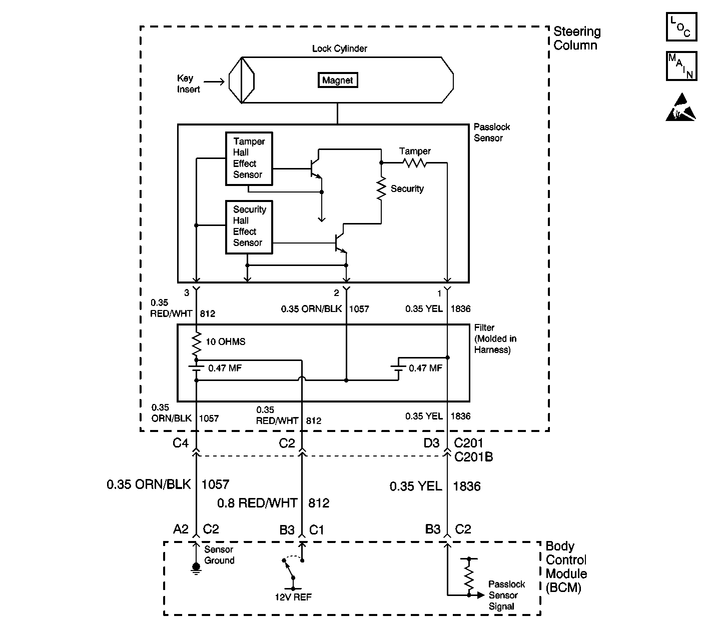
Circuit Description
The body control module (BCM) will read an analog voltage from the Passlock™ sensor. Based on an internal reference, the BCM will determine if the measured voltage is in one of the following conditions:
| • | Open |
| • | Shorted to ground |
| • | A valid code |
| • | A tamper code |
There are 10 possible valid code combinations. The BCM will only recognize the last learned valid code.
Conditions for Setting the DTC
| • | The ignition switch is ON. |
| • | The BCM signal input is less than 0.4 volts for 1 second after turning the ignition switch to the CRANK position. |
Action Taken When the DTC Sets
| • | The vehicle will not start if the fault occurs before you start the vehicle. The security telltale will flash for 10 minutes then turn ON steady. |
| • | If the vehicle is running when the fault occurs, the BCM will be in the fail enable mode allowing the vehicle to start and run. The security telltale will be ON. |
Conditions for Clearing the DTC
| • | The DTC will clear once the ignition cycle has occurred without the fault recurring. |
| • | The BCM history codes will clear once 100 concurrent ignition cycles occur without the fault recurring. |
| • | Using a scan tool. |
Diagnostic Aids
| • | When replacing the Passlock™ sensor, all of the following components are included as a replacement part and must be replaced: |
| - | The lock |
| - | The sensor |
| - | The filter |
| - | The harness |
| • | Use a scan tool in order to inspect the Passlock™ data voltage and the Passlock™ code. |
| • | Inspect the Passlock™ sensor harness for an intermittent or a short to battery. Refer to Testing for Intermittent Conditions and Poor Connections in Wiring Systems. |
| • | Following a repair the tamper timer needs 10 minutes in order to expire. |
Test Description
The numbers below refer to the step numbers on the diagnostic table.
-
Tests for proper operation of the circuit in the high voltage range.
-
Tests for a short to ground in the Passlock™ sensor signal circuit.
Step | Action | Value(s) | Yes | No | ||||||||||||||||||||||||
|---|---|---|---|---|---|---|---|---|---|---|---|---|---|---|---|---|---|---|---|---|---|---|---|---|---|---|---|---|
1 | Did you perform the Theft Deterrent (VTD) Diagnostic System Check? | -- | Go to Step 2 | |||||||||||||||||||||||||
2 |
Does the scan tool indicate that the Passlock™ data voltage is within the specified range? | 0.4-4.9v | Go to Testing for Intermittent Conditions and Poor Connections | Go to Step 3 | ||||||||||||||||||||||||
Does the scan tool indicate that the Passlock™ data voltage is greater than the specified value? | 4.9v | Go to Step 7 | Go to Step 4 | |||||||||||||||||||||||||
Test the Passlock™ sensor signal circuit for a short to ground. Refer to Circuit Testing and Wiring Repairs in Wiring Systems. Did you find and correct the condition? | -- | Go to Step 10 | Go to Step 5 | |||||||||||||||||||||||||
5 | Inspect for poor connections at the BCM. Refer to Testing for Intermittent Conditions and Poor Connections and Connector Repairs in Wiring Systems. Did you find and correct the condition? | -- | Go to Step 10 | Go to Step 6 | ||||||||||||||||||||||||
6 |
Important: Perform the set up procedure for the body control module . Replace the body control module. Refer to Body Control Module Replacement in Body Control Systems. Did you complete the replacement? | -- | Go to Step 10 | -- | ||||||||||||||||||||||||
7 | Inspect for poor connections at the Passlock™ sensor. Refer to Testing for Intermittent Conditions and Poor Connections and Connector Repairs in Wiring Systems. Did you find and correct the condition? | -- | Go to Step 10 | Go to Step 8 | ||||||||||||||||||||||||
8 | Replace the Passlock™ sensor in the electronic column lock module assembly. Use the appropriate procedure from the following list:
Did you complete the replacement? | -- | Go to Step 9 | -- | ||||||||||||||||||||||||
9 | Perform one of the following Passlock™ learn procedures:
Is the repair complete? | -- | Go to Step 10 | -- | ||||||||||||||||||||||||
10 |
Does the DTC reset? | -- | Go to Step 3 | System OK |
