For 1990-2009 cars only
Electronic Column Lock Module - Disassemble - Off Vehicle Floor shift Export
Tools Required
J-42759 Ignition Switch Connector Release Tool
- Remove the turn signal cancel cam, bearing thrust washer. Refer to Turn Signal Cancel Cam and Bearing Thrust Washer - Disassemble - Off Vehicle .
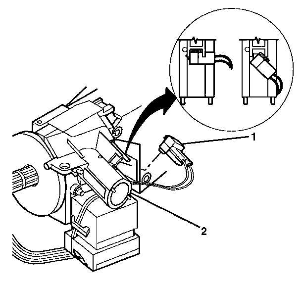
- Remove the key alarm connector (1) from the electronic lock module assembly (2) in the following way:
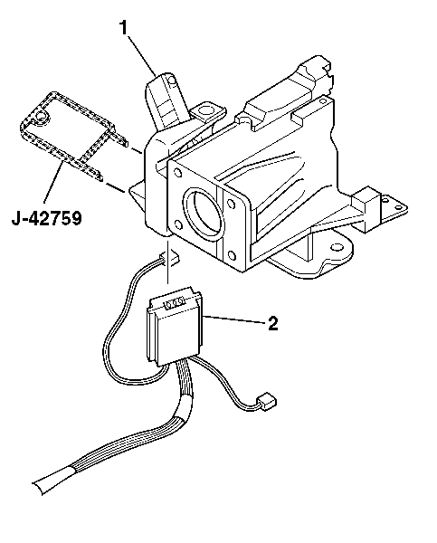
- Insert J-42759 into the electronic lock module and slide the ignition and key alarm switch assembly (2) out.
- Let the ignition and key alarm switch assembly (2) hang freely.
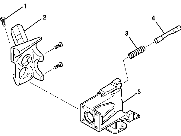
- Remove the 3 pan head tapping screws (1) from the electronic lock module assembly (2).
- Remove the electronic lock module assembly (2) and the lock bolt assembly (4) from the steering column housing assembly (5).
- Remove the lock bolt spring (3) from the lock bolt assembly (4).

| 2.1. | Rotate the key alarm connector (1) 90 degrees. |
| 2.2. | Pull the key alarm connector (1) out of the electronic lock module assembly (2). |
| 2.3. | Remove the passkey connector from the electronic lock module assembly (2). |


Important: The lock bolt assembly (4) is under slight spring tension from the lock bolt spring (3). Hold the lock bolt (4) in place while removing the electronic lock module assembly (2).
Electronic Column Lock Module - Disassemble - Off Vehicle Column shift Export
- Remove the turn signal cancel cam, bearing thrust washer. Refer to Turn Signal Cancel Cam and Bearing Thrust Washer - Disassemble - Off Vehicle .
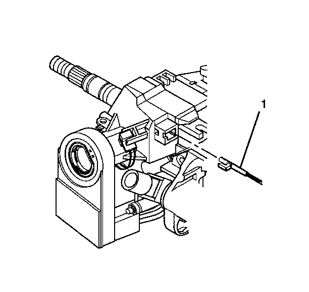
- Remove the park lock cable assembly (1) from the electronic lock module assembly.
- Rotate the key alarm connector (1) 90 degrees.
- Pull the key alarm connector (1) out of the electronic lock module assembly (2).
- Remove the passkey connector from the electronic lock module assembly (2).
- Insert J-42759 into the electronic lock module (1) and slide the ignition and key alarm switch assembly (2) out.
- Let the ignition and key alarm switch assembly (2) hang freely.
- Remove the 3 pan head tapping screws (1) from the electronic lock module assembly (2).
- Remove the electronic lock module assembly (2) and the lock bolt assembly (4) from the steering column housing assembly (5).
- Remove the lock bolt spring (3) from the electronic lock bolt assembly (4).

| 2.1. | Place the steering column lock cylinder set into the OFF position. |
| 2.2. | Place the shift lever clevis into the PARK position. |
| 2.3. | Use a small blade to push against the locking tab on the end of the park lock cable assembly (1). |
| 2.4. | Disconnect the park lock cable assembly (1) from the electronic lock module assembly. |


Important: The lock bolt assembly (4) is under slight spring tension from the lock bolt spring (3). Hold the lock bolt (4) in place while removing the electronic lock module assembly (2).
