Circuit Description
An exhaust gas recirculation (EGR) system is used in order to lower oxides of nitrogen (NOx) emission levels caused by high combustion temperatures. The EGR accomplishes this by feeding small amounts of exhaust gases back into the combustion chamber. When the air/fuel mixture is diluted with the exhaust gases, combustion temperatures are reduced.
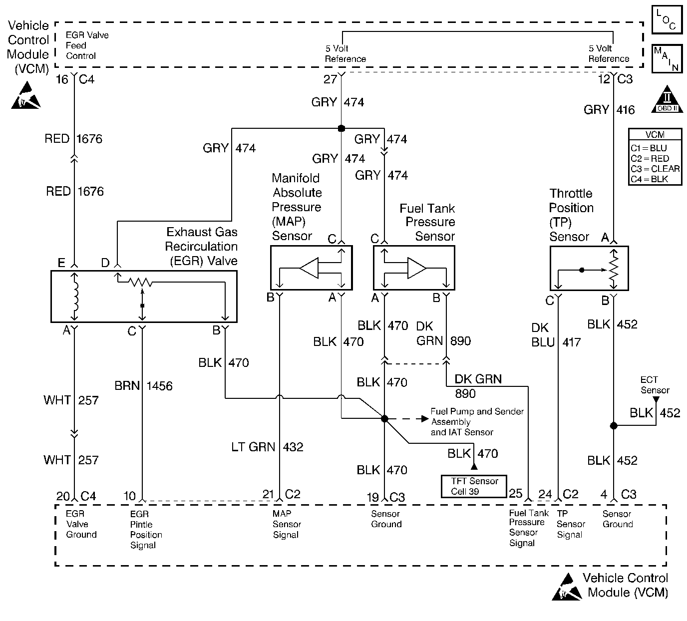
A linear EGR valve is used on this system. The linear EGR valve is designed in order to accurately supply exhaust gases to the engine without the use of intake manifold vacuum. The valve controls exhaust flow going into the intake manifold from the exhaust manifold through an orifice with a control module controlled pintle valve. The control module commands the EGR by applying a 12 volt duty cycle to the EGR valve. This can be monitored on a scan tool as desired EGR position.
The control module can monitor the pintle position with the EGR pintle position signal. This sensor uses a variable resistor with a 5 volt reference, a signal circuit, and a ground. The signal circuit monitors changes in voltage on the variable resistor as the pintle moves.
The VCM will set a DTC P0404 if it detects a large enough difference between desired EGR and actual EGR.
Conditions for Running the DTC
Ignition voltage more than 9 volts.
Conditions for Setting the DTC
The difference between the actual EGR position and the desired EGR position is greater than 10 percent for more than 10 seconds
Action Taken When the DTC Sets
| • | The control module illuminates the malfunction indicator lamp (MIL) the first time the diagnostic runs and fails. |
| • | The control module will set the DTC and records the operating conditions at the time the diagnostic fails. The control module stores the failure information in the scan tools Freeze Frame/Failure Records. |
Conditions for Clearing the MIL or DTC
| • | The control module turns OFF the MIL after 3 consecutive drive trips when the test has run and passed. |
| • | A history DTC will clear if no fault conditions have been detected for 40 warm-up cycles. A warm-up cycle occurs when the coolant temperature has risen 22°C (40°F) from the startup coolant temperature and the engine coolant reaches a temperature that is more than 70°C (158°F) during the same ignition cycle. |
| • | Use a scan tool in order to clear the DTCs. |
Diagnostic Aids
Excessive carbon deposits may cause a restriction of movement in the EGR pintle. This problem may be compounded in cold weather with moisture freezing in the valve. Check for full operation in the EGR system with the scan tool.
Check for excessive exhaust back pressure. Refer to Restricted Exhaust System Check .
An intermittent may be caused by any of the following conditions:
| • | A poor connection |
| • | Rubbed through wire insulation |
| • | A broken wire inside the insulation |
Thoroughly check any circuitry that is suspected of causing the intermittent complaint. Refer to Intermittents and Poor Connections Diagnosis in Wiring Systems.
If a repair is necessary, refer to Wiring Repairs or Connector Repairs in Wiring Systems.
Test Description
Number(s) below refer to the step number(s) on the Diagnostic Table.
-
This step will determine if the VCM can control the EGR valve.
-
Commanding the EGR valve to the specified values determines whether the VCM can control the EGR valve accurately. Production variations may not allow the EGR valve to be commanded to 100%.
-
There are certain circuits in the VCM C4 connector that could cause a short to voltage to the EGR valve control circuit that may disappear when the C4 connector is disconnected. By checking each individual circuit for a short to the EGR valve control circuit with a DMM will confirm if such a condition exists.
-
If the EGR valve 5 volt reference is shorted to voltage, the DMM will read battery voltage and additional DTCs may be set.
-
A problem may exist within the terminals which would not show up in probe type testing. Be sure to check the terminals for being backed out, improperly formed, or damaged.
-
A problem may exist within the terminals which would not show up in probe type testing. Be sure to check the terminals for being backed out, improperly formed, or damaged.
-
Clearing the DTCs is a very important step for this diagnostic. The clearing function allows the EGR valve to relearn a new minimum pintle position.
Step | Action | Value(s) | Yes | No |
|---|---|---|---|---|
1 |
Important: Before clearing the DTCs, use the scan tool Capture Info to save the Freeze Frame and Failure Records for reference. The control module's data is deleted once the Clear Info function is used. Did you perform the Powertrain On-Board Diagnostic System Check? | -- | ||
Does the engine run rough or stall? | 50% | |||
Does the actual EGR position closely follow the commanded position? | 0%, 20%, 50%, 70%, 100% | |||
4 | This DTC is intermittent. Are any other DTCs set? | -- | Go to the applicable DTC table | Go to Diagnostic Aids |
5 |
Is the test lamp ON? | 100% | ||
6 | Probe the EGR valve ground circuit at the EGR valve harness connector with a test lamp connected to B+. Is the test lamp ON? | -- | ||
7 |
Did you find a problem? | -- | ||
8 |
Did you find a problem? | -- | ||
9 |
Did you find a problem? | -- | ||
10 |
Caution: Avoid contact with moving parts and hot surfaces while working around a running engine in order to prevent physical injury. Is the test lamp ON? | -- | ||
11 |
Is the test lamp ON? | -- | ||
Are there any circuits shorted to the EGR valve control circuit? | -- | |||
Measure voltage between the 5 volt reference circuit at the EGR valve harness connector and a ground with a J 39200 DMM. Is the voltage above the specified value? | 5.2 V | |||
14 | Measure the voltage on the EGR valve pintle position signal circuit at the EGR valve harness connector with a J 39200 DMM connected to a ground. Is the voltage at the specified value? | 0 V | ||
15 |
Did you find a problem? | -- | ||
16 | Probe the EGR sensor ground circuit at the EGR valve harness connector with a test lamp connected to B+. Is the test lamp ON? | -- | ||
17 | Repair the short to voltage to the EGR valve control circuit. Refer to Wiring Repairs in Wiring Systems. Is the action complete? | -- | -- | |
18 | Repair the short to the EGR valve control circuit. Refer to Wiring Repairs or Connector Repairs in Wiring Systems. Is the action complete? | -- | -- | |
19 | Repair the short to voltage in the 5 volt reference circuit. Refer to Wiring Repairs in Wiring Systems. Is the action complete? | -- | -- | |
20 |
Did you find a problem? | -- | ||
Check for a poor connection at the EGR valve. Refer to Connector Repairs in Wiring Systems. Did you find a problem? | -- | |||
22 | Replace the EGR valve. Refer to Exhaust Gas Recirculation Valve Replacement . Is the action complete? | -- | -- | |
Check the VCM connectors for a poor connection. Repair as necessary. Refer to Connector Repairs in Wiring Systems. Did you find a problem? | -- | |||
24 |
Is the action complete? | -- | -- | |
Does the scan tool indicate the diagnostic Passed? | ||||
26 | Does the scan tool display any additional undiagnosed DTCs? | -- | Go to the applicable DTC table | System OK |
