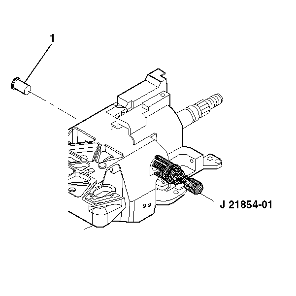
Special Tools
J21854 - 01 Pivot Pin Remover
Removal Procedure
- Disable the SIR coil. Refer to SIR Disabling and Enabling.
- Remove the steering wheel from the column. Refer to Steering Wheel Replacement.
- Remove the steering column from the vehicle. Refer to Steering Column Replacement.
- Remove the turn signal and multifunction switch assembly only. Refer to Turn Signal Multifunction Switch Replacement.
- Remove the wire harness assembly only. Refer to Steering Column Wiring Harness Replacement.
- Remove the telescope drive motor assembly and cable only. Refer to Telescope Actuator Assembly Replacement.
- Remove the tilt drive motor assembly and cable only. Refer to Tilt Motor Replacement.
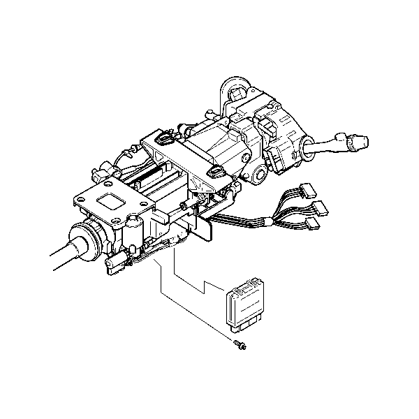
- Remove 1 TORX® head screw from the control module.
- Slide the control module out from the steering column.
- Remove the following components:
- The steering wheel position sensor (1). Refer to Steering Wheel Position Sensor Centering.
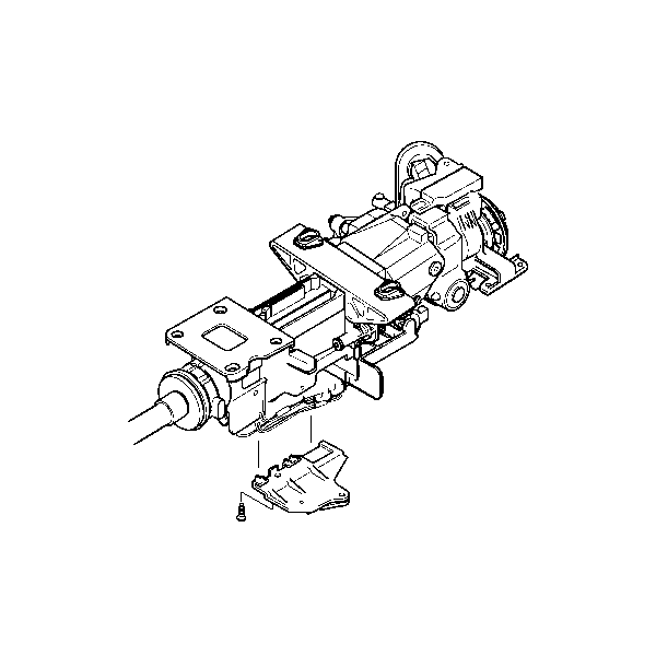
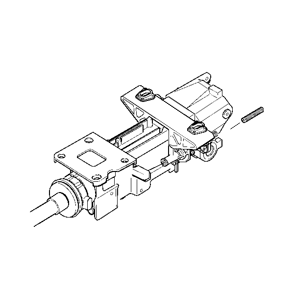
- Remove 1 TORX® Head Screw from the bottom of the gearshift and tilt motor bracket.
- Remove the bracket.
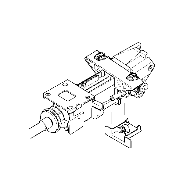
- Gently pry the lower shield assembly off of the steering column.
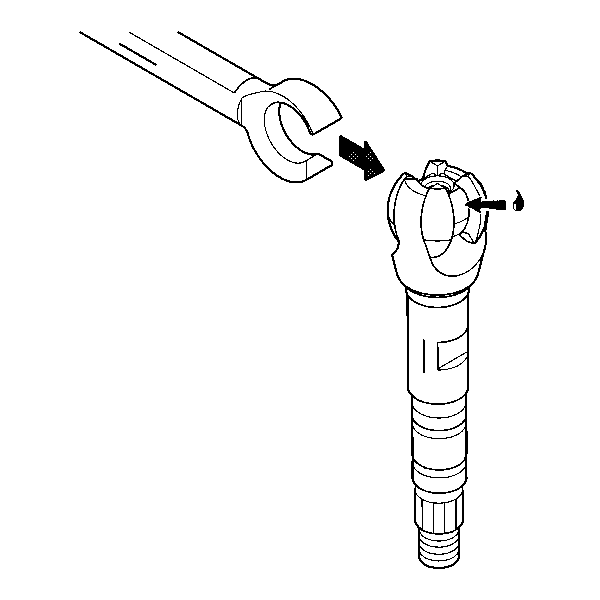
- Remove 2 pivot pins (1) from the steering column support assembly using J21854 - 01 .
- Unscrew the lead screw.
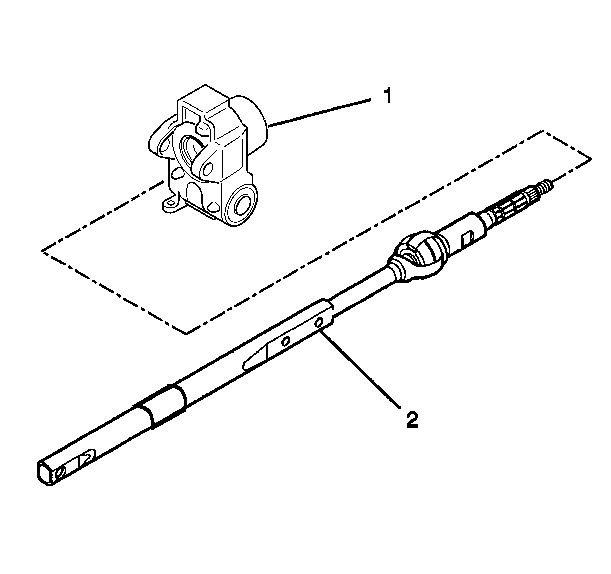
- Remove the tilt head assembly (1) from the steering column support assembly (2) with the steering shaft (3) still attached.
- Remove the tilt head assembly (1) from the steering shaft assembly (2).
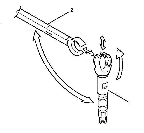
- Tilt the upper shaft assembly 90 degrees to the steering shaft assembly and disengage.
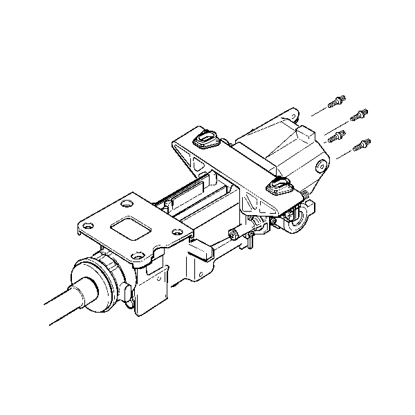
- Remove 2 TORX® Head Screws from the dampener.
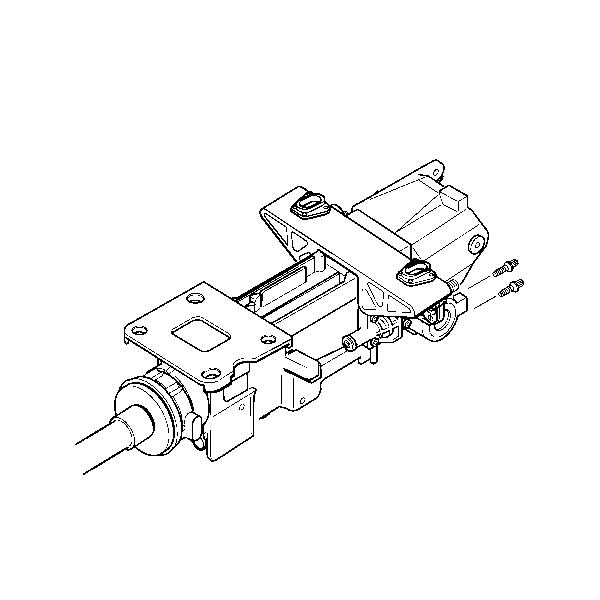
- Remove and discard 4 support screws from the steering column support.
- Remove the steering column support.
- Inspect the steering column for accident damage.
Warning: Refer to SIR Warning in the Preface section.
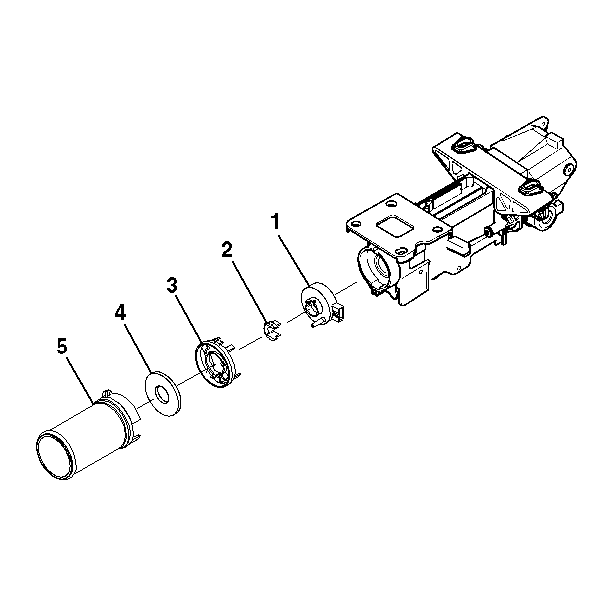
| 10.1. | The boot seal (5) |
| 10.2. | The steering shaft seal (4) |
| 10.3. | The sensor retainer (3) |
| 10.4. | The sensor locator (2) |

Note: Mark the race and upper shaft (1) and the lower steering shaft (2) to ensure proper assembly. Failure to assemble properly will cause the steering wheel to be turned 180 degrees.
Installation Procedure
- Install the steering column support and secure the support using 4 support screws.
- Install 2 TORX® Head Screws into the dampener.
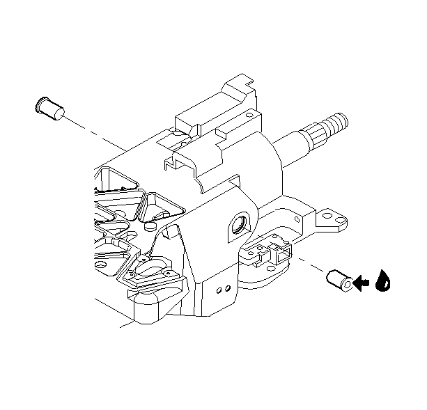
- Apply GM P/N 12345718 (Canadian P/N 10953516) to the race and upper shaft assembly.
- Align the marks on the race and upper shaft assembly with the lower shaft assembly.
- Install the lower shaft assembly to the race and upper shaft assembly.
- Install the steering shaft assembly (2) into the tilt head assembly (1).
- Install the tilt head assembly (1) and the steering shaft assembly (3) into the jacket assembly (2).
- Install the lead screw.
- Lubricate the pivot pins with GM P/N 12345718 (Canadian P/N 10953516).
- Align and snap the lower shield assembly onto the steering column.
- Install the bracket.
- Remove 1 TORX® head screw from the bottom of the gearshift and tilt motor bracket.
- Install the following components:
- Slide the control module into position.
- Install 1 retaining screw.
- Install the tilt drive motor assembly and cable only. Refer to Tilt Motor Replacement.
- Install the telescope drive motor assembly and cable only. Refer to Telescope Actuator Assembly Replacement.
- Install the turn signal and multifunction switch assembly only. Refer to Turn Signal Multifunction Switch Replacement.
- Install the wire harness assembly only. Refer to Steering Column Wiring Harness Replacement.
- Install the steering column into the vehicle. Refer to Steering Column Replacement.
- Install the steering wheel onto the steering column. Refer to Steering Wheel Replacement.
- Enable the SIR system. Refer to SIR Disabling and Enabling.
Caution: Refer to Fastener Caution in the Preface section.
Tighten
Tighten the bolts to 17 N·m (13 lb ft).
Tighten
Tighten the screw to 1.5 N·m (13 lb in).
Note: Use the alignment marks from the disassemble procedure. Failure to assemble properly will cause the steering wheel to be turned 180 degrees.
Install the 2 pivot pins onto the steering column support assembly.
Tighten
Tighten the screw to 3 N·m (27 lb in).
| 13.1. | The steering wheel position sensor (1). Refer to Steering Wheel Position Sensor Centering. |
| 13.2. | The sensor locator (2) |
| 13.3. | The sensor retainer (3) |
| 13.4. | The steering shaft seal (4) |
| 13.5. | The boot seal (5) |
Tighten
Tighten the screw to 5 N·m (44 lb in).
Warning: Refer to SIR Inflator Module Coil Warning in the Preface section.
