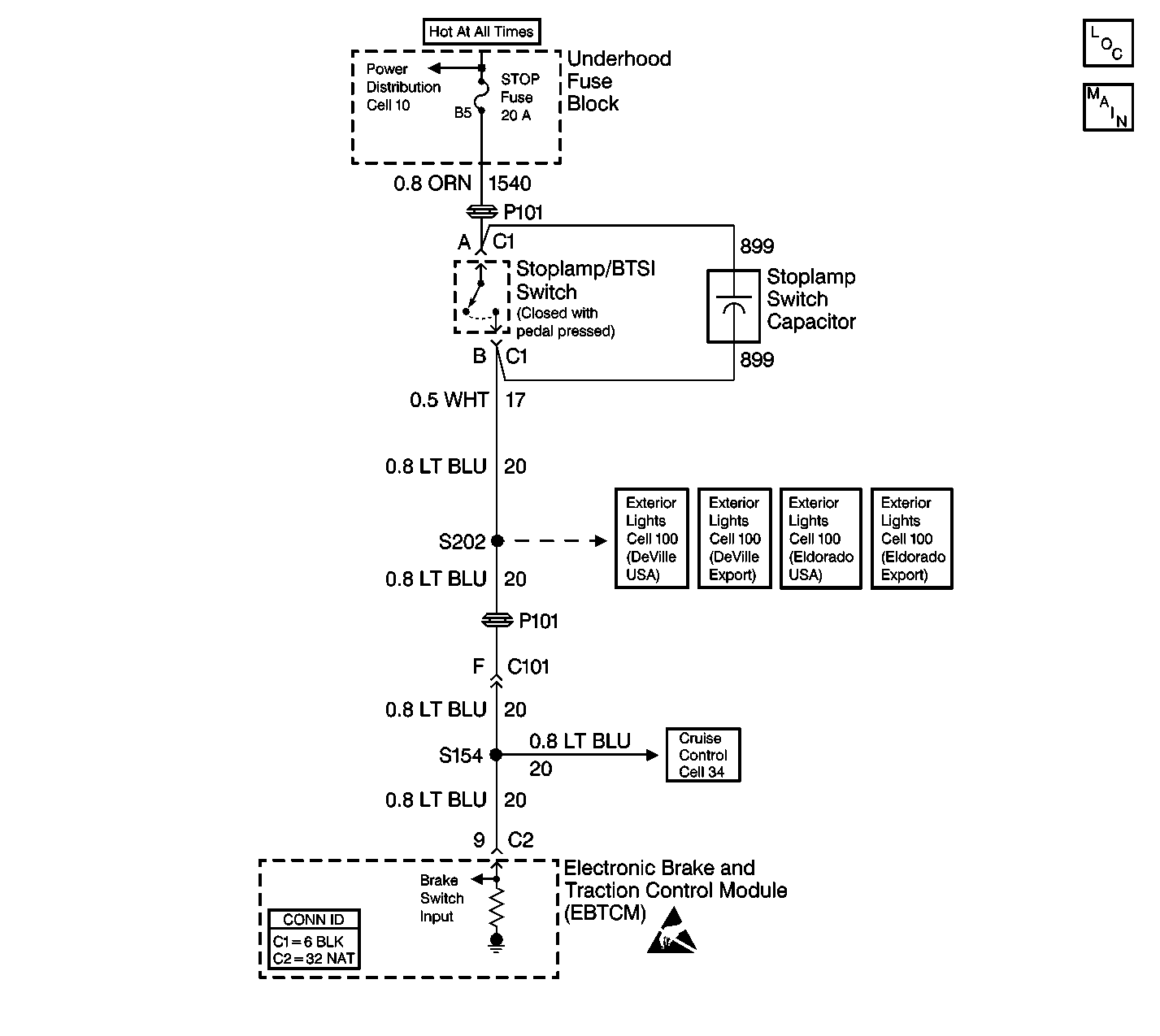
Circuit Description
This DTC occurs when the internal self-checking safety logic has determined that the stoplamp/BTSI switch is continuously on. The TCS cannot be activated when the stoplamp/BTSI switch is on.
Conditions for Setting the DTC
The DTC sets if the following occur:
| • | The vehicle speed is greater than 40 km/h (25 mph). |
| • | The brake was never off during 2 consecutive drive cycles. |
Action Taken When the DTC Sets
| • | A malfunction DTC is stored. |
| • | The TCS is disabled. |
| • | The TRACTION CONTROL indicator is turned ON. |
| • | The ABS remains functional. |
Conditions for Clearing the DTC
| • | The condition for DTC is no longer present and you used scan tool Clear DTCs function. |
| • | The condition for DTC is no longer present and you used the On-Board Clear DTCs function. |
| • | The EBTCM does not detect the DTC in 50 drive cycles. |
Diagnostic Aids
| • | It is very important that a thorough inspection of the wiring and connectors be performed. Failure to carefully and fully inspect wiring and connectors may result in misdiagnosis, causing part replacement with reappearance of the malfunction. |
| • | An intermittent malfunction can be caused by poor connections, broken insulation, or a wire that is broken inside the insulation. |
| • | If an intermittent malfunction exists, refer to Intermittents and Poor Connections . |
| • | This condition may be cause by the following: |
| - | A short to voltage in the stoplamp/BTSI switch circuit. |
| - | A misadjusted or shorted stoplamp/BTSI switch. |
| - | A pedal that is binding. |
Test Description
The numbers below refer to the step numbers on the diagnostic table.
Step | Action | Value(s) | Yes | No |
|---|---|---|---|---|
1 | Was the Diagnostic System Check performed? | -- | Go to Step 2 | Go to Diagnostic System Check |
2 | Observe the rear brake lamps. Are the rear brake lamps off? | -- | Go to Step 4 | Go to Step 3 |
3 | Disconnect the brake lamp switch connector. Are the brake lamps on? | -- | Go to Step 6 | Go to Step 7 |
Is the voltage greater than the specified value? | 1 V | Go to Step 6 | Go to Step 5 | |
5 |
Was DTC C1294 set in the last three drive cycles? | -- | Go to Step 8 | Go to Diagnostic System Check |
6 | Repair the short to voltage in CKT 20. Refer to Wiring Repairs in Wiring Systems. Is the circuit repair complete? | -- | Go to Diagnostic System Check | -- |
7 | Adjust or replace the stoplamp/BTSI switch as necessary. Refer to Stop Lamp Switch Adjustment or Stop Lamp Switch Replacement in Hydraulic Brakes. Is the repair complete? | -- | Go to Diagnostic System Check | -- |
8 | Replace the EBTCM. Refer to Electronic Brake Control Module Replacement . Is the replacement complete? | -- | Go to Diagnostic System Check | - |
