Exhaust Manifold Replacement - Left Side L26
Removal Procedure
- Disconnect the negative battery cable. Refer to Battery Negative Cable Disconnection and Connection.
- Remove the fuel injector sight shield. Refer to Fuel Injector Sight Shield Replacement.
- Remove the engine mount struts. Refer to Engine Mount Strut Replacement - Right Side and Engine Mount Strut Replacement - Left Side.
- Remove the lower right engine mount strut bracket. Refer to Engine Mount Strut Bracket Replacement - Right Side.
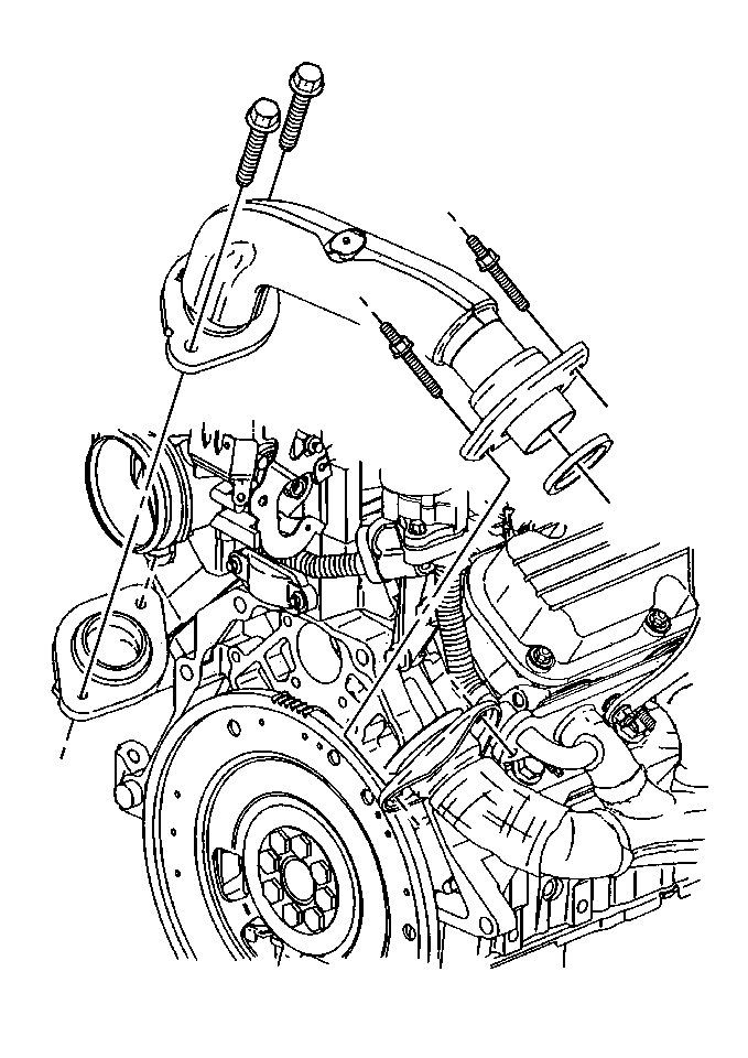
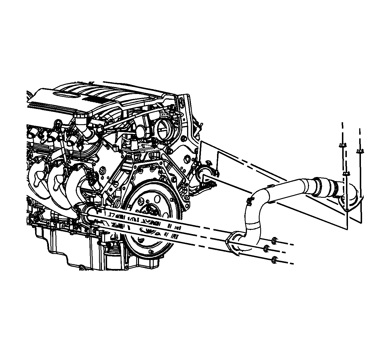
- Remove the exhaust crossover pipe bolts from the left exhaust manifold.
- Remove the left spark plugs from cylinders 1, 3 and 5. Refer to Spark Plug Replacement.
- Remove the oil level indicator tube. Refer to Oil Level Indicator and Tube Replacement.
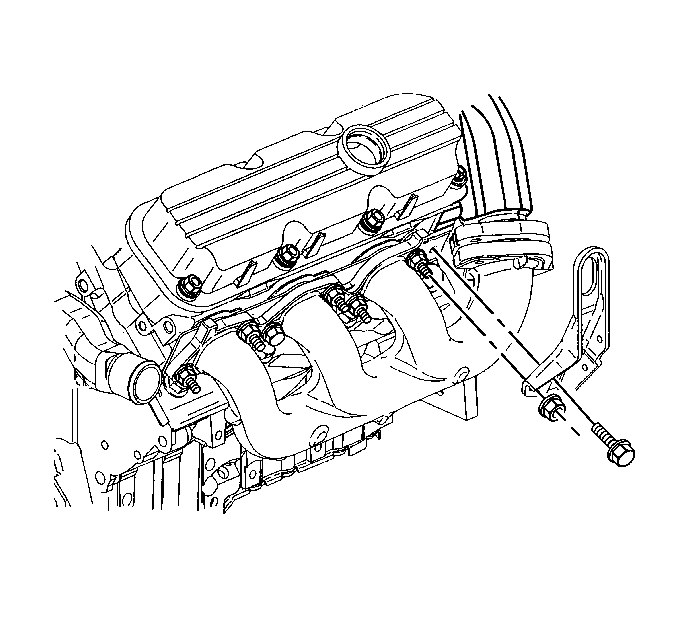
- Remove the left engine lift bracket bolt and the nut.
- Remove the left engine lift bracket
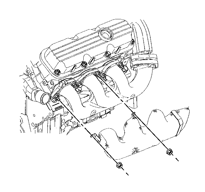
- Remove the exhaust manifold heat shield nuts.
- Remove the exhaust manifold heat shield.
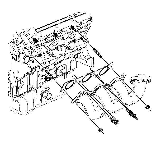
- Remove the exhaust manifold bolts and the nuts.
- Remove the exhaust manifold.
- Remove the exhaust manifold gasket.
- Clean and inspect the left exhaust manifold. Refer to Exhaust Manifold Cleaning and Inspection.
Installation Procedure
- Install the new exhaust manifold gasket.
- Install the exhaust manifold.
- Install the exhaust manifold bolts and the nuts.
- Install the exhaust manifold heat shield.
- Install the exhaust manifold heat shield nuts.
- Install the engine lift bracket.
- Install the engine lift bracket bolt and the nut.
- Install the oil level indicator tube. Refer to Oil Level Indicator and Tube Replacement.
- Install the left spark plugs to cylinders 1, 3 and 5. Refer to Spark Plug Replacement.
- Install the exhaust crossover bolts to the left exhaust manifold.
- Install the lower right engine mount strut bracket. Refer to Engine Mount Strut Bracket Replacement - Right Side.
- Install the engine mount struts. Refer to Engine Mount Strut Replacement - Right Side and Engine Mount Strut Replacement - Left Side.
- Install the fuel injector sight shield. Refer to Fuel Injector Sight Shield Replacement.
- Connect the negative battery cable. Refer to Battery Negative Cable Disconnection and Connection.

Caution: Refer to Fastener Caution in the Preface section.
Tighten
Tighten the bolts and the nuts to 30 N·m (22 lb ft).

Tighten
Tighten the nuts to 20 N·m (15 lb ft).

Tighten
Tighten the bolt and the nut to 30 N·m (22 lb ft).

Tighten
Tighten the bolts to 20 N·m (15 lb ft).
Exhaust Manifold Replacement - Left Side LS4
Removal Procedure
- Remove the engine sight shield. Refer to Upper Intake Manifold Sight Shield Replacement.
- Remove the exhaust crossover pipe heat shield in order to access the cross pipe to the exhaust manifold nuts.
- Remove the exhaust crossover pipe nuts from the left exhaust manifold.
- Remove the left side spark plugs. Refer to Spark Plug Replacement.
- Remove the oil level indicator tube. Refer to Oil Level Indicator and Tube Replacement.
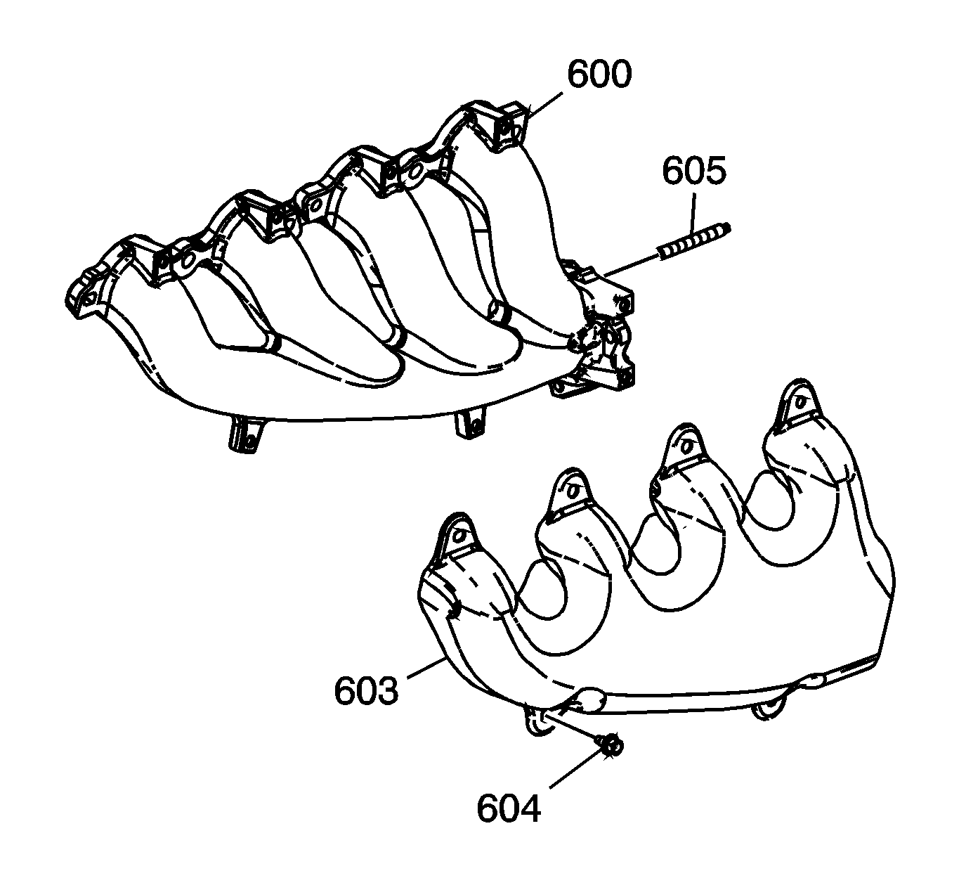
- Remove the exhaust manifold heat shield bolts (604).
- Remove the exhaust manifold heat shield (603).
- Remove the heater hose retainer bolts in order to be able to remove the manifold.
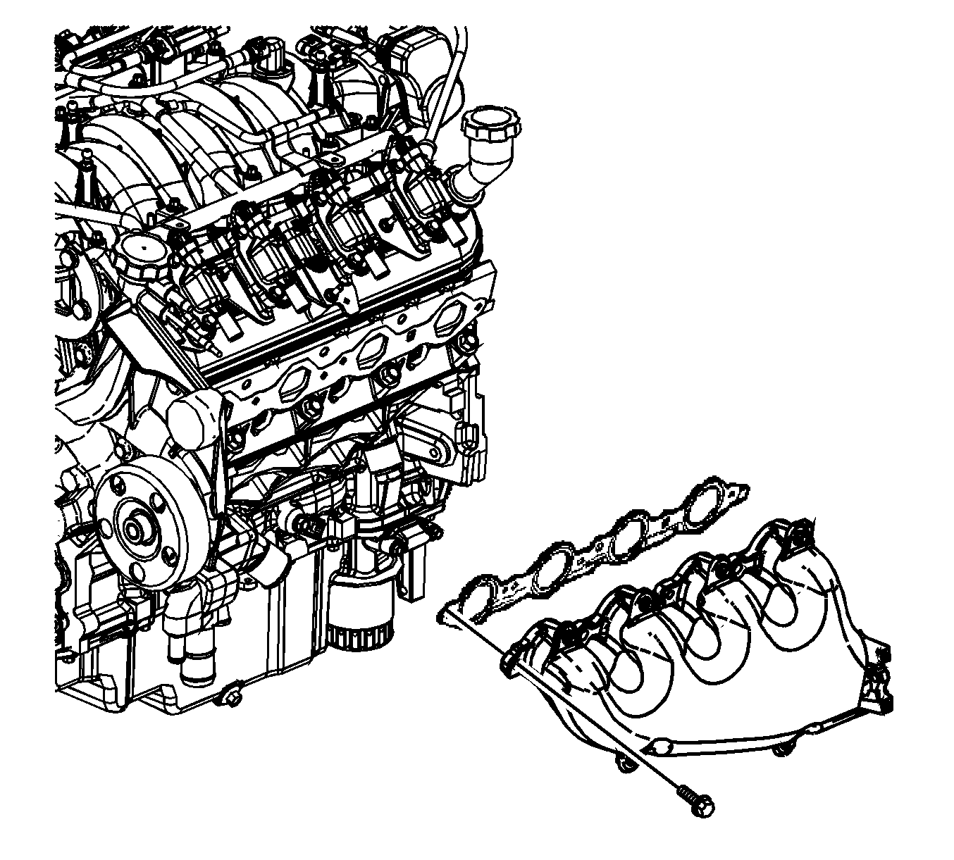
- Remove the exhaust manifold bolts.
- Remove the exhaust manifold.
- Remove and discard the exhaust manifold gasket.
Installation Procedure
Note:
• Tighten the exhaust manifold bolts as specified in the service procedure. Improperly installed and/or leaking exhaust manifold gaskets my affect vehicle emissions and/or On Board Diagnostic (OBD) II system performance. • The cylinder head exhaust manifold bolt hole threads must be clean and free of debris or threadlocking material. • DO NOT apply threadlock to the first three thread of the bolts.
- Apply a 5 mm (0.2 in) wide band of threadlock GM P/N 12345493 (Canadian P/N 10953488) or equivalent to the threads of the exhaust manifold bolts.
- Install a NEW exhaust manifold gasket, the exhaust manifold and bolts.
- Using a flat punch, bend over the exposed edge of the exhaust manifold gasket at the rear of the left cylinder head.
- Install the exhaust manifold heat shield (603).
- Install the exhaust manifold heat shield bolts (604).
- Install the oil level indicator tube. Refer to Oil Level Indicator and Tube Replacement.
- Install the left side spark plugs. Refer to Spark Plug Replacement.
- Install the exhaust crossover pipe nuts from the left exhaust manifold.
- Install the exhaust crossover pipe heat shield.
- Install the heater pipe retainer bolts.
- Install the engine sight shield. Refer to Upper Intake Manifold Sight Shield Replacement.

Caution: Refer to Fastener Caution in the Preface section.
Tighten
| • | Tighten the bolts a first pass to 15 N·m (11 lb ft). Tighten the bolts beginning with the center 2 bolts. Alternate from side to side, and work toward the outside. |
| • | Tighten the bolts a final pass to 20 N·m (15 lb ft). Tighten the bolts beginning with the center 2 bolts. Alternate from side to side, and work toward the outside. |

Tighten
Tighten the bolts to 9 N·m (80 lb in).

Tighten
Tighten the nuts to 25 N·m (18 lb ft).
Tighten
Tighten the bolts to 16 N·m (12 lb ft).
