Special Tools
| • | J 41665
Crankshaft Balancer and Sprocket Installer |
| • | J 41816
Crankshaft Balancer Remover |
| • | J 42640
Steering Column Anti-Rotation Pin |
Removal Procedure
- Install a
J 42640
. Refer to
Steering Column Replacement.
- Remove the accessory drive belt. Refer to
Drive Belt Replacement - Accessory.
- Remove the air cleaner upper housing. Refer to
Air Cleaner Assembly Replacement.
- Remove the engine mount strut. Refer to
Engine Mount Strut Replacement.
- Remove the starter motor. Refer to
Starter Replacement.
- Remove the front fender splash shield.
- Disconnect the transaxle cooler lines at the transaxle. Refer to
Transmission Fluid Cooler Hose/Pipe Quick-Connect Fitting Disconnection and Connection.
- Remove the stabilizer shaft link lower nuts. Refer to
Stabilizer Shaft Link Replacement.
- Remove the intermediate steering shaft pinch bolt and separate the shaft from the steering gear. Refer to
Intermediate Steering Shaft Replacement.
- Remove the front lower air deflector braces and the deflector. Refer to
Radiator Air Lower Baffle and Deflector Replacement.
- Remove the radiator to frame braces.
- Install the engine support fixture. Refer to
Engine Support Fixture.
- Raise and support the vehicle. Refer to
Lifting and Jacking the Vehicle.
- Remove the frame-to-body bolts.
- Remove the transmission-to-engine bolt located at approximately the 10 o'clock position when looking from the rear of the engine.
Caution: Refer to Fastener Caution in the Preface section.
- Install the
EN 47699
and bolt to the block and flywheel.
Tighten
Tighten the bolt to 60 N·m (44 lb ft).
- Remove the right front tire and wheel assembly. Refer to
Tire and Wheel Removal and Installation.
- Lower the engine approximately 100 mm (4 in).
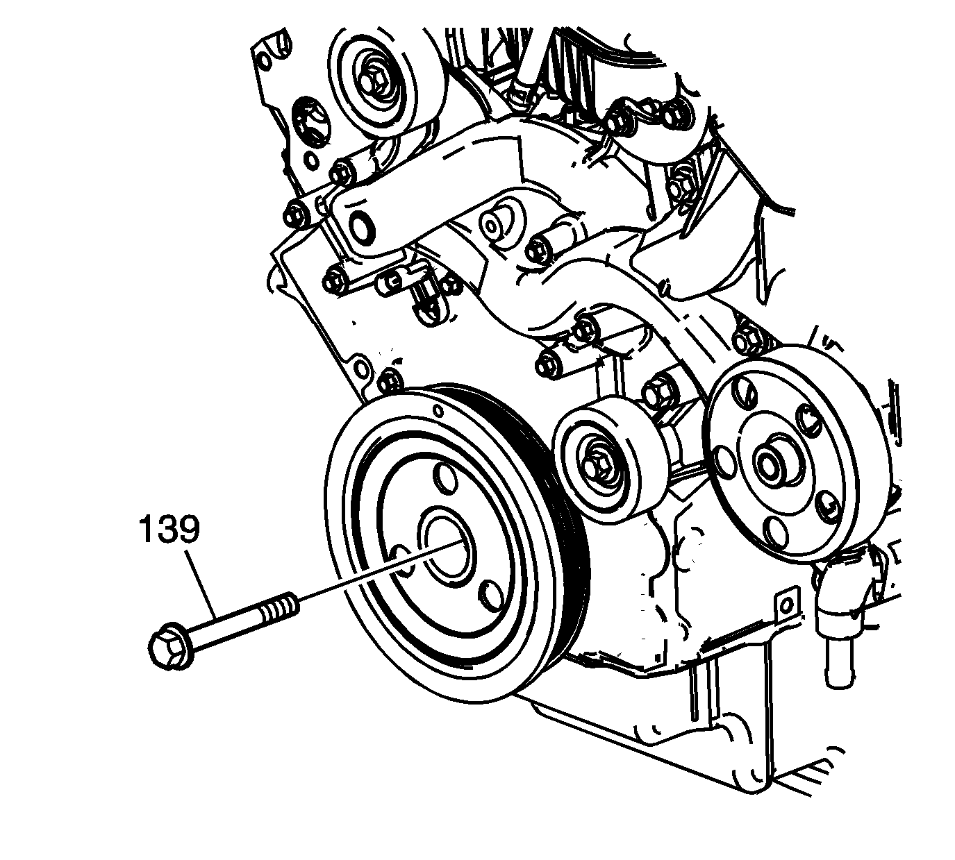
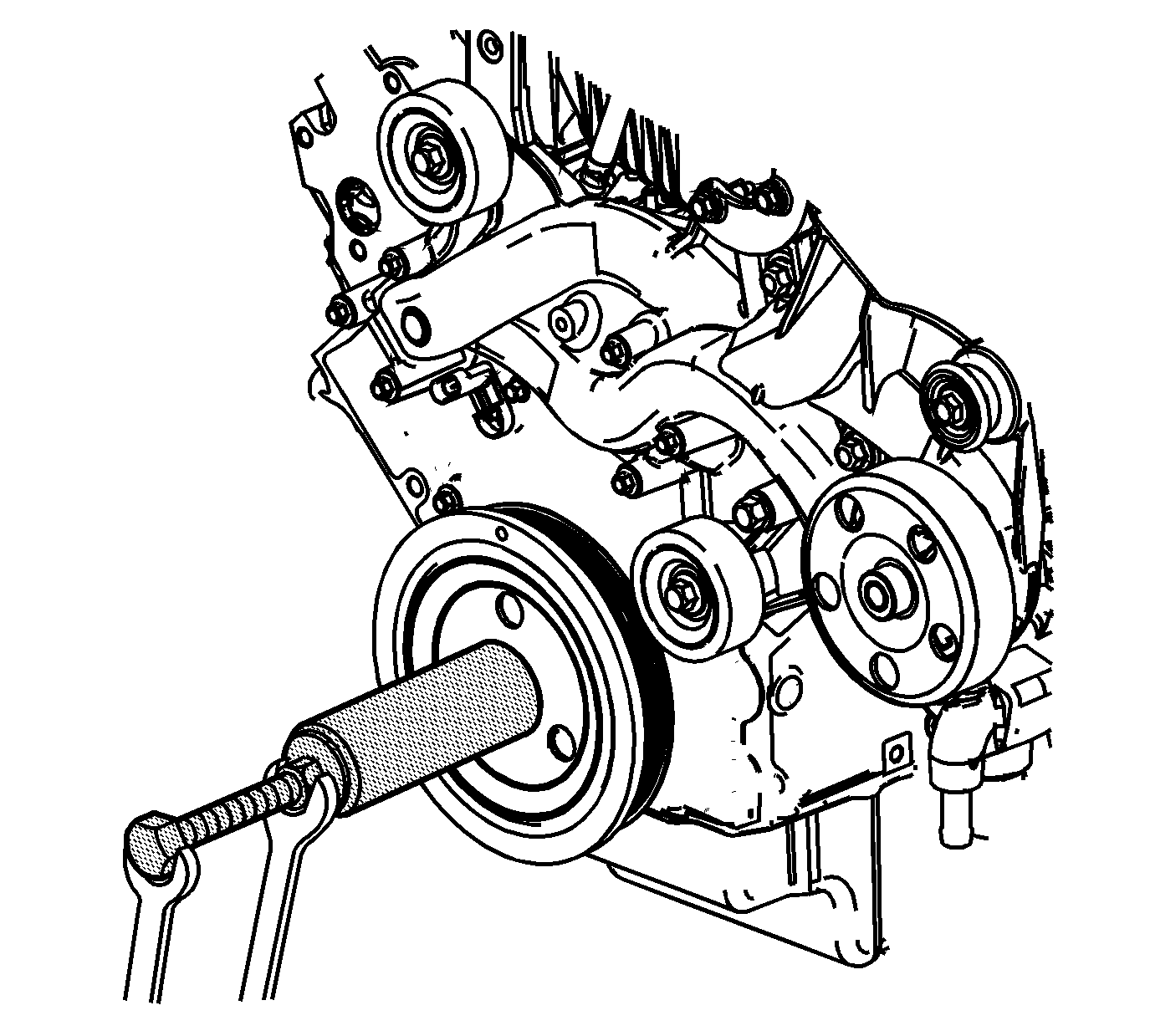
- Remove the crankshaft balancer bolt (139).
Do not discard the crankshaft balancer bolt.
The balancer bolt will be used during the balancer installation procedure.
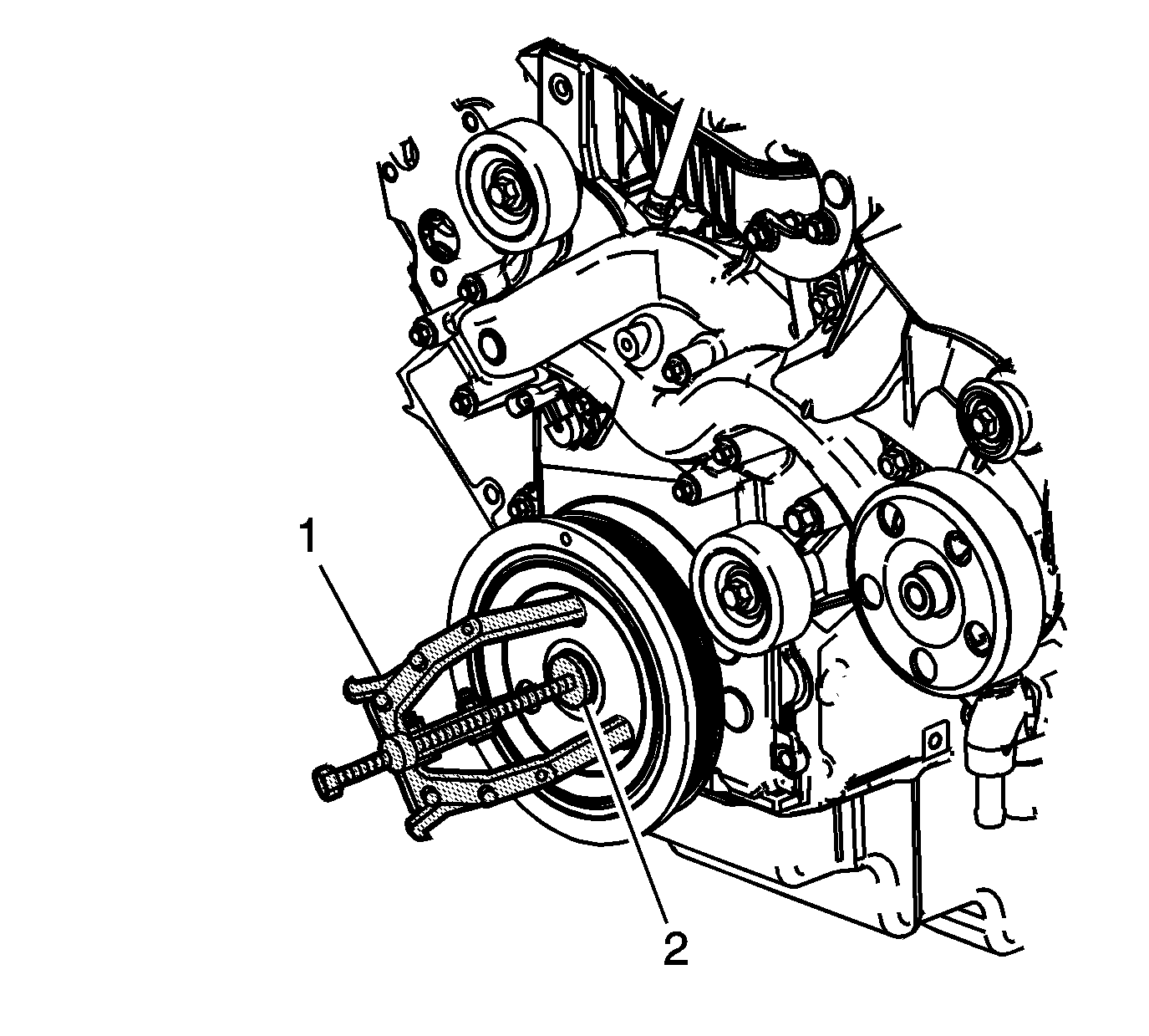
- Install the
J 41816
(1) and the
J 41816-2
(2), to the crankshaft balancer.
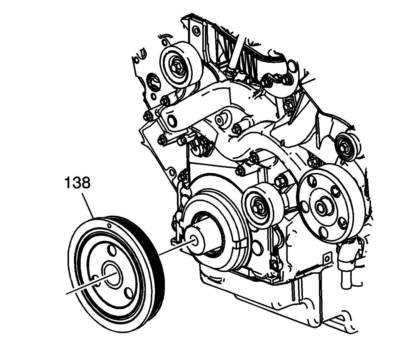
- Remove the crankshaft balancer (138).
- Remove the
J 41816
and the
J 41816-2
from the crankshaft balancer.
Installation Procedure
Note:
| • | The used crankshaft balancer bolt will be used only during the first pass of the balancer installation procedure. Install a NEW bolt and tighten as described in the second, third and forth passes of the balancer bolt tightening procedure. |
| • | The crankshaft balancer installation and bolt tightening involves a four stage tightening process. The first pass ensures that the balancer is installed completely onto the crankshaft. The second, third, and forth passes tighten the new bolt to the
proper torque. |
| • | The balancer should be positioned onto the end of the crankshaft as straight as possible prior to tool installation. |
- Position the crankshaft balancer (138) onto the end of the crankshaft.
- Using the
J 41665
, install the crankshaft balancer.
| 2.1. | Assemble the threaded rod, nut, washer and installer. Insert the smaller end of the installer into the front of the balancer. |
| 2.2. | Use a wrench and hold the hex end of the threaded rod. |
| 2.3. | Use a second wrench and rotate the installation tool nut clockwise until the balancer is started onto the crankshaft. |
| 2.4. | Remove the tool and reverse the installation tool. Position the larger end of the installer against the front of the balancer. |
| 2.5. | Use a wrench and hold the hex end of the threaded rod. |
| 2.6. | Use a second wrench and rotate the installation tool nut clockwise until the balancer is installed onto the crankshaft. |
| 2.7. | Remove the balancer installation tool. |
Caution: Refer to Fastener Caution in the Preface section.
- Install the USED crankshaft balancer bolt (139).
Tighten
Tighten the USED bolt to 330 N·m (240 lb ft).
- Remove the USED crankshaft balancer bolt.
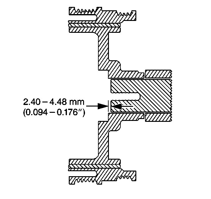
Note: The nose of the crankshaft should be recessed 2.4-4.48 mm (0.094-0.176 in) into the balancer bore.
- Measure for a correctly installed balancer. If the balancer is not installed to the proper dimensions, install the
J 41665
and repeat the installation procedure.
- Install a NEW crankshaft balancer bolt (139).
Tighten
| • | Tighten the bolt a first pass to 50 N·m (37 lb ft). |
| • | Tighten the bolt a second pass to 140 degrees using
J 45059
. |
- Remove the
EN 47699
and bolt from the block and flywheel.
- Install the transmission bellhousing bolt located at approximately the 10 o'clock position when looking from the rear of the engine.
Tighten
Tighten the bolt to 75 N·m (55 lb ft).
- Raise and properly position the frame and install the frame to body bolts. Refer to
Frame Replacement.
- Install the frame to radiator braces.
- Install the front lower air deflector. Refer to
Radiator Air Lower Baffle and Deflector Replacement.
- Connect the intermediate steering shaft to the steering gear. Refer to
Intermediate Steering Shaft Replacement.
- Install the stabilizer shaft link lower nuts. Refer to
Stabilizer Shaft Link Replacement.
- Connect the transaxle cooler lines to the transaxle. Refer to
Transmission Fluid Cooler Hose/Pipe Quick-Connect Fitting Disconnection and Connection.
- Remove the engine support fixture.
- Install the front fender splash shield.
- Install the starter motor. Refer to
Starter Replacement.
- Install the air cleaner upper housing. Refer to
Air Cleaner Assembly Replacement.
- Install the accessory drive belt. Refer to
Drive Belt Replacement - Accessory.
- Install the engine mount strut. Refer to
Engine Mount Strut Replacement.
- Install the right front tire and wheel assembly. Refer to
Tire and Wheel Removal and Installation.
- Perform the crankshaft position (CKP) system variation learn procedure.
