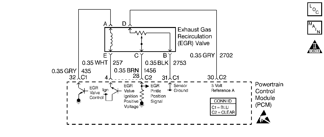
Circuit Description
The PCM monitors the EGR valve pintle position input to ensure that the valve responds properly to commands from the PCM. The Linear EGR valve is controlled by using an ignition positive driver and ground circuit within the PCM. The driver has the ability to detect an electrical malfunction in the ignition positive or ground circuit. If an electrical malfunction occurs, the driver signals the PCM to set DTC P0403.
Conditions for Running the DTC
| • | No TP, IAT, MAP, ECT, CKP, MAF sensor, VSS, Misfire, Idle Speed, Fuel Injector, or DTCs set. |
| • | Engine coolant temperature is greater than 75°C (167°F). |
| • | Engine run time met. The time ranges from 20 seconds to 6 minutes depending upon engine coolant temperature at startup. |
| • | TP angle is greater than 2%. |
| • | Vehicle speed is greater than 2 mph (3.2 km/h) |
| • | System voltage is between 10 volts and 18 volts. |
Conditions for Setting the DTC
| • | The PCM detects an electrical malfunction in the control circuit for the EGR Valve. |
| • | The condition is present for more than 20 second. |
Action Taken When the DTC Sets
| • | The PCM will illuminate the malfunction indicator lamp (MIL) during the second consecuitive trip in which the diagnostic has been run and failed. |
| • | If equipped with traction control, the PCM will command the EBTCM via the serial data circuit to turn OFF traction control, and the EBTCM will illuminate the TRACTION OFF lamp. |
| • | The PCM will store conditions which were present when the DTC set as Freeze Frame and Failure Records data. |
Conditions for Clearing the MIL/DTC
| • | The PCM will turn OFF the MIL during the third consecutive trip in which the diagnostic has been run and passed. |
| • | The History DTC will clear after 40 consecutive warm-up cycles have occurred without a malfunction. |
| • | The DTC can be cleared by using the scan tool. |
Diagnostic Aids
| • | Poor connection at PCM or EGR Valve. Refer to Intermittents and Poor Connections Diagnosis . |
| Inspect harness connectors for backed out terminals, improper mating, broken locks, improperly formed or damaged terminals, and poor terminal to wire connection. Refer to Intermittents and Poor Connections Diagnosis . |
| • | Damaged harness. Refer to Wiring Repairs . |
| Inspect the wiring harness for damage. If the harness appears to be OK, connect J 39200 DMM and check circuit continuity while moving connectors and wiring harnesses related to the EGR valve. A change in the display will indicate the location of the malfunction. Refer to Wiring Repairs . |
Test Description
Number(s) below refer to the step number(s) on the Diagnostic Table:
-
Verifies that the malfunction is present.
-
If DTC P0403 will only set under certain conditions, the malfunction may be intermittent, refer to Diagnostic Aids. If an intermittent wiring problem is not present, check for a poor connection at the PCM or the EGR valve.
-
This vehicle is equipped with a PCM which utilizes an Electrically Erasable Programmable Read Only Memory (EEPROM). When the PCM is being replaced, the new PCM must be programmed.
Step | Action | Value(s) | Yes | No | ||||||
|---|---|---|---|---|---|---|---|---|---|---|
1 | Was the Powertrain OBD System Check performed? | -- | ||||||||
With the engine idling, observe Actual EGR Position on the scan tool. Is Actual EGR Position at the specified value? | 0% | |||||||||
Does Desired EGR Position remain close to Actual EGR Position at all commanded positions? | -- | |||||||||
Does the scan tool indicate DTC P0403 failed this ignition? | -- | Go to Diagnostic Aids | ||||||||
5 |
Is the J 35616-200 test light on with the commanded EGR valve position at 100%? | -- | ||||||||
6 | Probe the EGR valve ground circuit at the EGR valve harness connector with a J 35616-200 test light to battery positive voltage. Is the J 35616-200 test light on? | -- | ||||||||
7 | Probe the EGR valve control circuit at the EGR valve harness connector with a J 35616-200 test light to battery positive voltage. Is the J 35616-200 test light on? | -- | ||||||||
8 |
Was a problem found? | -- | ||||||||
9 |
Is the J 35616-200 test light on? | -- | ||||||||
10 |
Was a problem found? | -- | ||||||||
11 | Replace the EGR valve. Refer to Exhaust Gas Recirculation Valve Replacement . Is the action complete? | -- | -- | |||||||
12 | Locate and repair the short to voltage in the EGR valve control circuit. Refer to Wiring Repairs . Is the action complete? | -- | -- | |||||||
13 |
Is the J 35616-200 test light on? | -- | ||||||||
14 |
Is the J 35616-200 test light on? | -- | ||||||||
15 |
Was a problem found? | -- | ||||||||
16 | Locate and repair the short to voltage in the EGR valve ground circuit. Refer to Wiring Repairs . Is the action complete? | -- | -- | |||||||
17 |
Was a problem found? | -- | ||||||||
18 | Locate and repair the short to ground in the EGR valve control circuit. Refer to Wiring Repairs . Is the action complete? | -- | -- | |||||||
19 |
Was a problem found? | -- | ||||||||
|
Important: : The replacement PCM must be programmed. Refer to Powertrain Control Module Replacement/Programming . Replace the PCM. Is the action complete? | -- | -- | ||||||||
21 |
Does the scan tool indicate DTC P0403 failed this ignition? | -- | System OK |
