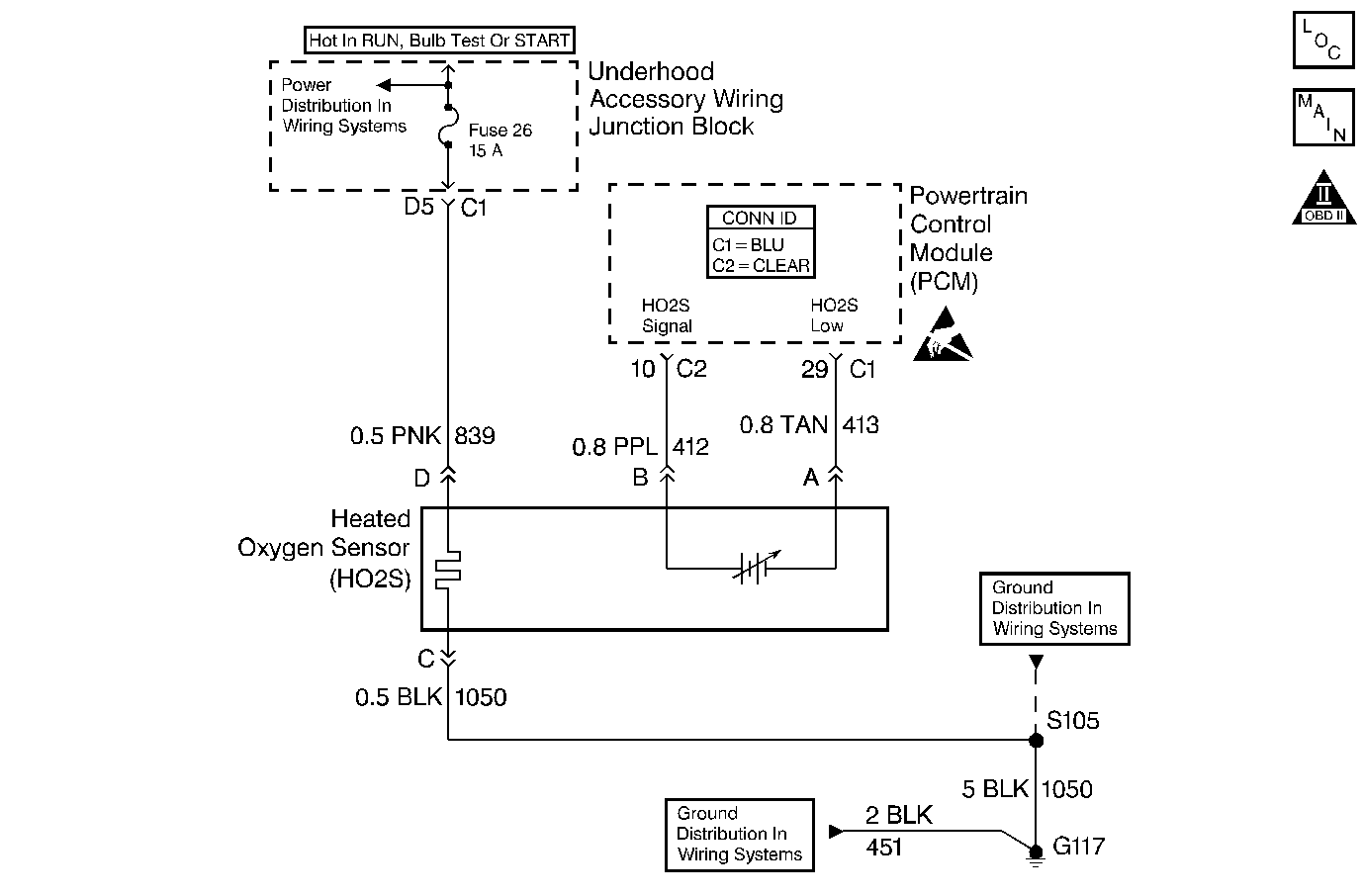
Circuit Description
The PCM supplies a bias voltage of about 450 mV between the HO2S signal and low circuits. When measured with a 10 megaohm digital voltmeter, this may display as low as 320 mV. The oxygen sensor varies the voltage within a range of about 1000 mV when the exhaust is rich, down through about 10 mV when exhaust is lean. The PCM constantly monitors the HO2S signal during closed loop operation and compensates for a rich or lean condition by decreasing or increasing injector pulse width as necessary. If the HO2S 1 voltage remains excessively high for an extended period of time, DTC P0132 will be set.
Conditions for Running the DTC
| • | No active TP, MAP, MAF, ECT, IAT, or CKP Sensor, misfire, fuel injector circuit, EVAP, EGR, DTCs present. |
| • | System Voltage is greater than 9.0 volts. |
| • | Closed loop commanded air/fuel ratio is between 14.4 and 14.9. |
| • | Throttle angle between 5% and 40%. |
Conditions for Setting the DTC
| • | HO2S 1 signal voltage remains above 975 mV for longer than 45 seconds during normal closed loop operation. |
| OR |
| • | HO2S 1 signal voltage remains above 200 mV for longer than 5 seconds during deceleration fuel mode operation. |
Action Taken When the DTC Sets
| • | The PCM will illuminate the malfunction indicator lamp (MIL) during the second consecuitive trip in which the diagnostic has been run and failed. |
| • | If equipped with traction control, the PCM will command the EBTCM via the serial data circuit to turn OFF traction control, and the EBTCM will illuminate the TRACTION OFF lamp. |
| • | The PCM will store conditions which were present when the DTC set as Freeze Frame and Failure Records data. |
Conditions for Clearing the MIL/DTC
| • | The PCM will turn OFF the MIL during the third consecutive trip in which the diagnostic has been run and passed. |
| • | The History DTC will clear after 40 consecutive warm-up cycles have occurred without a malfunction. |
| • | The DTC can be cleared by using the scan tool. |
Diagnostic Aids
Check the following items:
| • | Fuel Pressure. The system will go rich if pressure is too high. The PCM can compensate for some increase. However, if fuel pressure is too high. Refer to Fuel System Pressure Test . |
| • | Perform Injector Balance Test. Refer to Fuel Injector Balance Test . |
| • | Check the EVAP Canister for Fuel Saturation. If full of fuel, check canister control and hoses. |
| • | Disconnect the MAF sensor and see if rich condition is corrected. If so, replace the MAF sensor. Refer to Mass Airflow Sensor Replacement . |
| • | Check for a leaking fuel pressure regulator diaphragm by checking vacuum line to regulator for the presence of fuel. |
| • | An intermittent TP sensor output will cause the system to go rich due to a false indication of the engine accelerating. |
| • | Shorted Heated Oxygen Sensor (HO2S). If the HO2S is internally shorted the HO2S voltage displayed on the scan tool will be over 1.0 volt. Disconnect the affected HO2S and jumper the HO2S low circuit to ground with the key ON , engine OFF. If the displayed HO2S voltage changes from over 1000 mV to around 450 mV, replace the HO2S. Silicon contamination of the HO2S can also cause a high HO2S voltage to be indicated. This condition is indicated by a powdery white deposit on the portion of the HO2S exposed to the exhaust stream. If contamination is noticed, replace the affected HO2S. Refer to Heated Oxygen Sensor Replacement . |
| • | Open HO2S Signal or Low Circuit or Faulty HO2S. A poor connection or open in the HO2S signal or low circuit can cause the DTC to set during deceleration fuel mode. An HO2S which is faulty and not allowing a full voltage swing between the rich and lean thresholds can also cause this condition. Operate the vehicle while monitoring the HO2S voltage with a scan tool. If the HO2S voltage is limited within a range between 300 mV to 600 mV, check the HO2S signal and low circuit wiring and associated terminal connections. If the wiring and connections are OK, replace the HO2S. Refer to Heated Oxygen Sensor Replacement . |
Test Description
The numbers below refer to the step numbers on the Diagnostic Table:
Step | Action | Value(s) | Yes | No |
|---|---|---|---|---|
1 | Was the Powertrain on Board Diagnostic (OBD) System Test performed? | -- | ||
2 |
Does the HO2S 1 voltage remain above the specified value? | 950 mV | ||
Operate vehicle in Decel fuel mode (vehicle speed above 25 mph, TP angle below 3%) while monitoring HO2S 1 voltage display on the scan tool HO2S data list. Does the HO2S 1 voltage remain above the specified value while in Decel fuel mode? | 800 mV | |||
4 |
Does scan tool indicate DTC P0132 failed this ignition? | -- | Go to Diagnostic Aids | |
5 | Disconnect HO2S 1 and jumper HO2S low circuit to ground. Does scan tool indicate HO2S 1 voltage near the specified value? | 450 mV | Refer to Diagnostic Aids | |
6 |
Does J 39200 DMM indicate a voltage greater than specified value? | 600 mV | ||
Repair short to voltage in the HO2S 1 signal circuit. Refer to Wiring Repairs . Is the action complete? | -- | -- | ||
8 |
Important: : Replacement PCM must be programmed. Refer to Powertrain Control Module Replacement/Programming . Replace the PCM. Is the action complete? | -- | -- | |
9 |
Does the scan tool indicate DTC P0132 failed this ignition? | -- | System OK |
