Tools Required
J 39194-B Heated Oxygen Sensor socket.
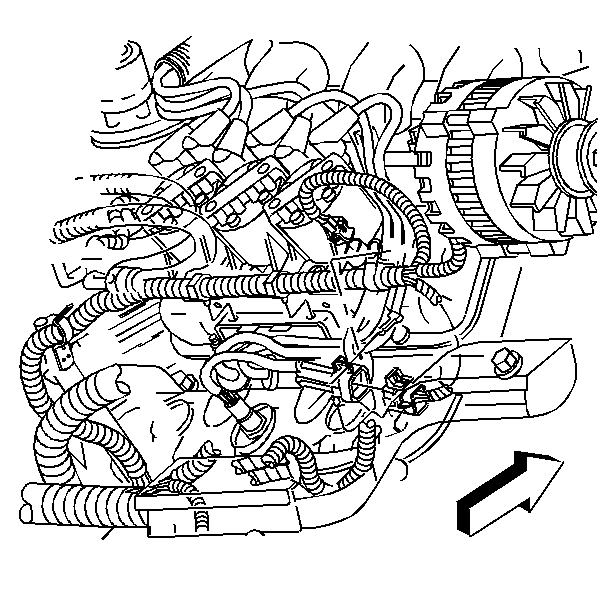
Removal Procedure (HO2S1)
The heated oxygen sensor may be difficult to remove when engine temperature is below 48°C (120°F). Excessive force may damage threads in exhaust manifold or exhaust pipe.
- Disconnect the electrical connector.
- Using J 39194-B Heated Oxygen Sensor socket carefully back out the heated oxygen sensor.
Important : A special anti seize compound is used on the heated oxygen sensor threads. The compound consists of graphite suspended in fluid and glass beads. The graphite will burn away, but the glass beads will remain, making the sensor easier to remove. New or service sensors will already have the compound applied to the threads. If a sensor is removed from an engine and if for any reason is to be reinstalled, the threads must have anti seize compound applied before reinstallation.
Installation Procedure (HO2S1)
- Coat the threads of heated oxygen sensor/catalyst monitor with anti seize compound P/N 5613695, or equivalent if necessary.
- Install the Heated Oxygen Sensor.
- Connect the electrical connector.
Notice: Use the correct fastener in the correct location. Replacement fasteners must be the correct part number for that application. Fasteners requiring replacement or fasteners requiring the use of thread locking compound or sealant are identified in the service procedure. Do not use paints, lubricants, or corrosion inhibitors on fasteners or fastener joint surfaces unless specified. These coatings affect fastener torque and joint clamping force and may damage the fastener. Use the correct tightening sequence and specifications when installing fasteners in order to avoid damage to parts and systems.
Tighten
Tighten the H02S 1 (Pre-catalytic converter) to 42 ±4 N·m
(31 lb ft).
