For 1990-2009 cars only
Removal Procedure
- Remove the left closeout insulator panel. Refer to Instrument Panel Insulator Panel Replacement - Left Side .
- Remove the knee bolster trim panel. Refer to Driver Knee Bolster Panel Replacement .
- Remove the instrument panel cluster (IPC) bezel. Refer to Instrument Panel Cluster Trim Plate Bezel Replacement .
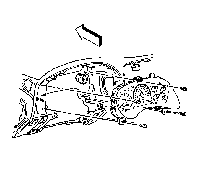
- Remove the screws retaining the IPC to the I/P.
- Partially remove the IPC from the I/P in order to gain access to the electrical connector.
- Disconnect the electrical connector from the IPC.
- Remove the IPC from the I/P.

Installation Procedure
- Position the IPC to the I/P.
- Connect the electrical connector to the IPC.
- Install the IPC to the I/P.
- Install the screws to the instrument panel cluster.
- Install the IPC bezel. Refer to Instrument Panel Cluster Trim Plate Bezel Replacement .
- Install the knee bolster trim panel. Refer to Driver Knee Bolster Panel Replacement .
- Install the left closeout insulator panel. Refer to Instrument Panel Insulator Panel Replacement - Left Side .
- If installing a new IPC, program the IPC. Refer to Control Module References in Computer/Integrating Systems.

Notice: Refer to Fastener Notice in the Preface section.
Tighten
Tighten the screws to 2.5 N·m (22 lb in).
