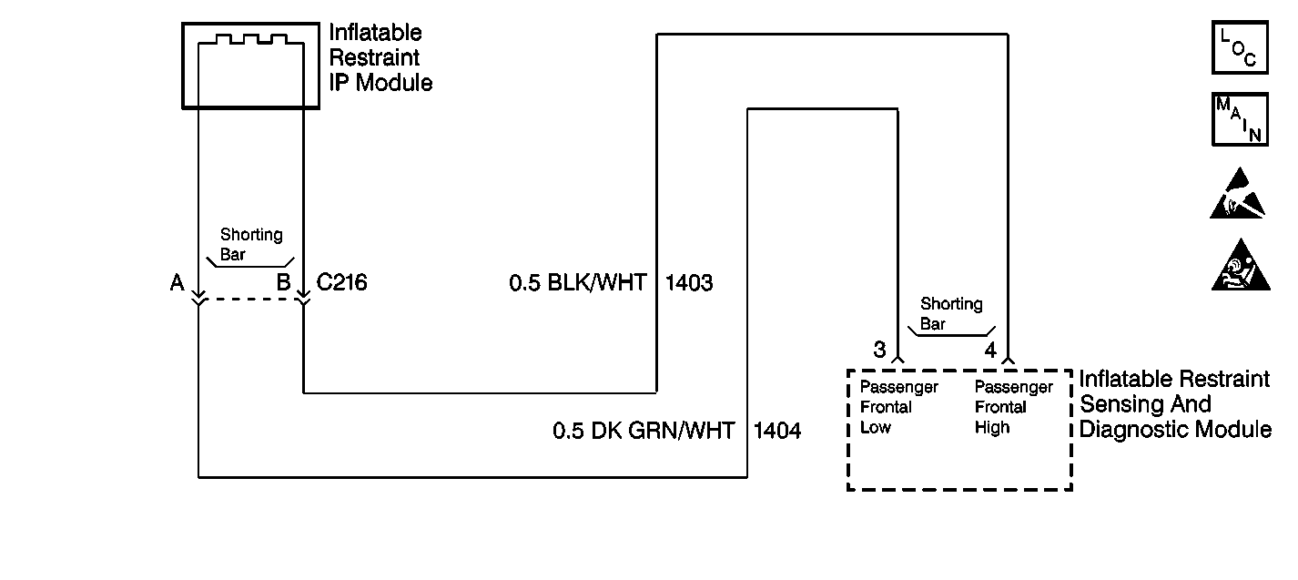
Circuit Description
When you first turn the ignition switch to the RUN position, the inflatable restraint sensing and diagnostic module (SDM) performs tests to diagnose critical malfunctions within itself. Next the SDM measures IGNITION voltage to make sure it is within its respective normal voltage range. Then the SDM proceeds with the DEPLOYMENT LOOP CONTINUITY test. During the DEPLOYMENT LOOP CONTINUITY test, the SDM measures the voltage difference between Passenger Frontal High and Passenger Frontal Low.
Conditions for Setting the DTC
| • | The passenger frontal air bag deployment loop resistance is more than 500 ohms. |
| • | The malfunction must be present for at least 500 milliseconds during one of the following tests: |
| - | DEPLOYMENT LOOP CONTINUITY |
| - | If the malfunction is detected in this test, the RESISTANCE MEASUREMENT test will not be performed. |
| - | CONTINUOUS MONITORING |
Action Taken When the DTC Sets
| • | The SDM sets a DTC B1017. |
| • | The SDM turns ON the AIR BAG warning lamp. |
Conditions for Clearing the DTC
| • | Current DTC |
| The resistance of the passenger frontal air bag deployment loop is less than 100 ohms for 500 milliseconds and the ignition switch is cycled. |
| • | History DTC |
| - | You issue a scan tool CLEAR CODES command. |
| - | Once 250 malfunction free ignition cycles have occurred. |
Diagnostic Aids
A poor connection can cause an intermittent condition. Check the following for a poor connection:
| • | The inflatable restraint IP module wiring harness connector terminal A and terminal B. |
| • | The SDM wiring harness conector terminal 3 and terminal 4. |
| • | An open in CKT 1403. |
| • | An open in CKT 1404. |
When measurements are requested in this table, use J 39200 Digital Multimeter with the correct terminal adapter from J 35616 Connector Test Adapter Kit. When a check for proper connection is requested, refer to Intermittents and Poor Connections . When a wire, connector or terminal repair is requested, use J-38125 Terminal Repair Kit and refer to Wiring Repair .
Test Description
The numbers below refer to the step numbers on the diagnostic table:
-
This step checks the inflatable restraint IP module yellow 2-way wiring harness connector for corrosion or damaged terminals.
-
This step isolates the malfunction to one side of the inflatable restraint IP module yellow 2-way connector.
-
This step checks the SDM wiring harness connector for corrosion or damaged terminals.
-
This step checks to see if there is an open in CKT 1403.
-
This step determines if there is an open in CKT 1404 or if there is a malfunctioning SDM.
Step | Action | Value(s) | Yes | No |
|---|---|---|---|---|
1 | Was the SIR Diagnostic System Check performed? | -- | ||
2 |
Has the PASSENGER FRONTAL VDIF been read and recorded on the repair order? | -- | -- | |
Are the terminals damaged or corroded? | -- | |||
4 | Replace the inflatable restraint IP module yellow 2-way wiring harness connector. Refer to Wiring Repair . Is the repair complete? | -- | -- | |
5 | Check for a proper connection at terminal A and terminal B of the inflatable restraint IP module yellow 2-way connector. Are the terminals damaged or corroded? | -- | ||
6 | Check for a proper connection at terminal A and terminal B of the inflatable restraint IP module yellow 2-way connector. Are the terminals damaged or corroded? | -- | ||
7 | Replace the inflatable restraint IP module. Refer to Inflatable Restraint Instrument Panel Module Replacement . Is the repair complete? | -- | -- | |
8 |
Is the PASSENGER FRONTAL VDIF less than the specified value? | 480 mV | ||
9 |
Is the repair complete? | -- | -- | |
Is the PASSENGER FRONTAL VDIF less than the specified value? | 480 mV | |||
11 |
Is the repair complete? | -- | -- | |
Is the connector damaged or corroded? | -- | |||
13 | Replace the SDM wiring harness connector. Refer to Wiring Repair . Is the repair complete? | -- | -- | |
14 | Check for a proper connection at terminal 3 and terminal 4 of the SDM. Are the terminals damaged or corroded? | -- | ||
15 | Check for a proper connection at terminal 3 and terminal 4 of the SDM. Are the terminals damaged or corroded? | -- | ||
16 | Replace the SDM Refer to Inflatable Restraint Sensing and Diagnostic Module Replacement . Is the repair complete? | -- | -- | |
Is the measured resistance within the specified value? | 0-0.5 ohms | |||
18 |
Is the repair complete? | -- | -- | |
Use the J 39200 to measure the resistance between terminal 3 of the SDM wiring harness connector and terminal A of the inflatable restraint IP module yellow 2-way connector. Is the measured resistance within the specified value? | 0-0.5 ohms | |||
20 |
Is the repair complete? | -- | -- | |
21 | Reconnect all the SIR system components, making sure all the components are properly mounted. Have all the SIR components been reconnected and properly mounted? | -- | -- | |
22 | Use the scan tool to clear all current and history SIR DTCs. Have all current and history SIR DTCs been cleared? | -- | -- |
