Electronic Ignition (EI)
The Electronic Ignition (EI) system on the 3400 LA1 (VIN E) engine uses a coil pack with one ignition coil for each two cylinders in the engine. Mounted under the ignition coils on each system is an Ignition Control Module (ICM) that performs ignition coil switching functions and interacts with the Powertrain Control Module (PCM) to optimize ignition system operation. On these engine systems, the spark timing is controlled electronically. The ICM controls the spark timing during engine start-up, and provides a back-up timing system that will allow the engine to run in the event of an open or ground in the Ignition Control (IC) circuit. Once the engine starts and is running above an approximate engine speed of 400 RPM, the PCM takes over the spark timing and sends signals to the ICM for ignition coil switching. The electronic ignition systems used on these engines use a waste spark method of spark distribution. Each cylinder is paired with its opposing cylinder in the firing order, so that one cylinder on compression fires simultaneously with the opposing cylinder on exhaust. The spark that occurs in the cylinder that is on the exhaust stroke is referred to as the waste spark. The spark plugs in the two opposing cylinders are connected to the two secondary terminals of the same ignition coil. The spark voltage appears at the center electrode of one of the spark plugs and jumps to the side electrode, then passes through the engine to the other spark plug. At the second spark plug, the spark jumps from the side electrode to the center electrode and completes the series circuit back to the ignition coil. The high level of energy available from the ignition coil is more than sufficient to fire both plugs simultaneously. Since the waste spark requires very little of the available voltage to fire, most of the coil output voltage is available to fire the cylinder that is on the compression stroke. Engine speed (RPM) and cylinder position in the intake-compression-power-exhaust sequence are sensed electronically and are used by the ICM and PCM to control timing. These parameters are provided by a magnetic Crankshaft Position (CKP) sensor mounted in the engine block. The magnetic CKP sensor consists of a wire coil wound around a permanent magnet. The sensor is positioned near a reluctor ring on the crankshaft. The reluctor ring has notches which trigger signals in the magnetic sensor to indicate Crankshaft Position (CKP) and crankshaft speed (RPM). These signals are used by the ICM during start up, then passed on to the PCM to help determine optimum timing while the engine is running. The PCM also uses other inputs separate from the ignition system itself, to determine optimum timing.
Secondary Ignition Wiring
The spark plug wiring used with ignition systems is a carbon impregnated cord conductor, encased in a 7 mm (9/32 in) or 8 mm (5/16 in) diameter silicone rubber jacket. The silicone jacket withstands very high temperatures. Silicone spark plug boots form a tight seal on the plug. The boot should be twisted 1/2 turn before removing. Care should also be used when connecting a timing light or other pick-up equipment. Do not force anything between the boot and wiring, or through the silicone jacket. Connections should be made in parallel using an adapter. Do not pull on the wire to remove. Pull on the boot, or use a tool designed for this purpose.
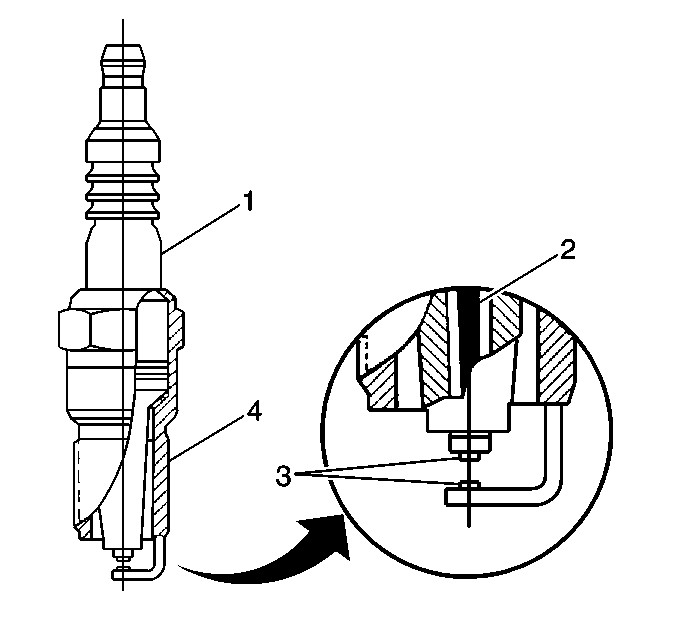
Spark Plugs
Extended Life Spark Plug (Typical)