For 1990-2009 cars only
Removal Procedure
Warning: Refer to Brake Fluid Irritant Warning in the Preface section.
Caution: Refer to Brake Fluid Effects on Paint and Electrical Components Caution in the Preface section.
- Turn the ignition switch to the OFF position.
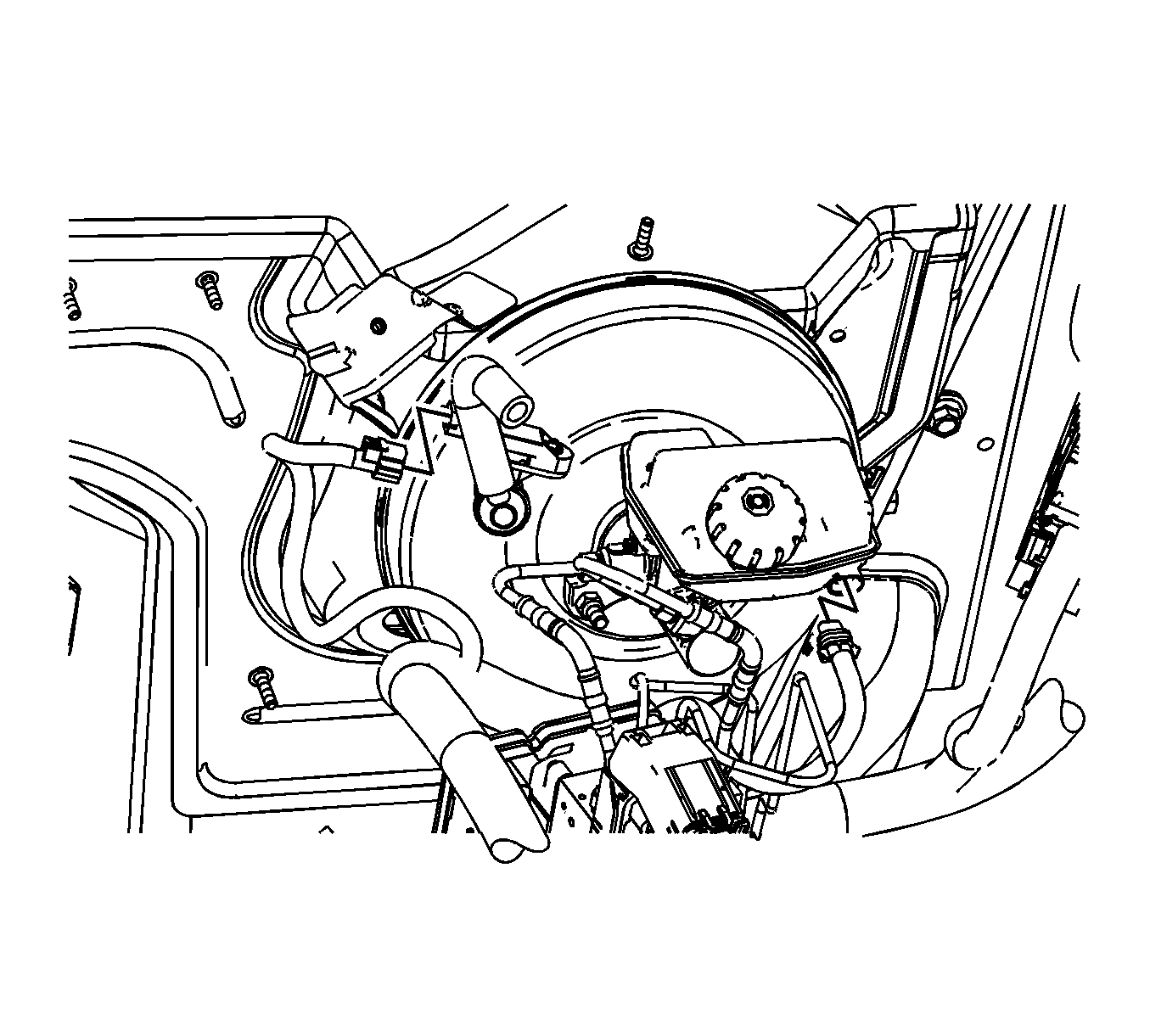
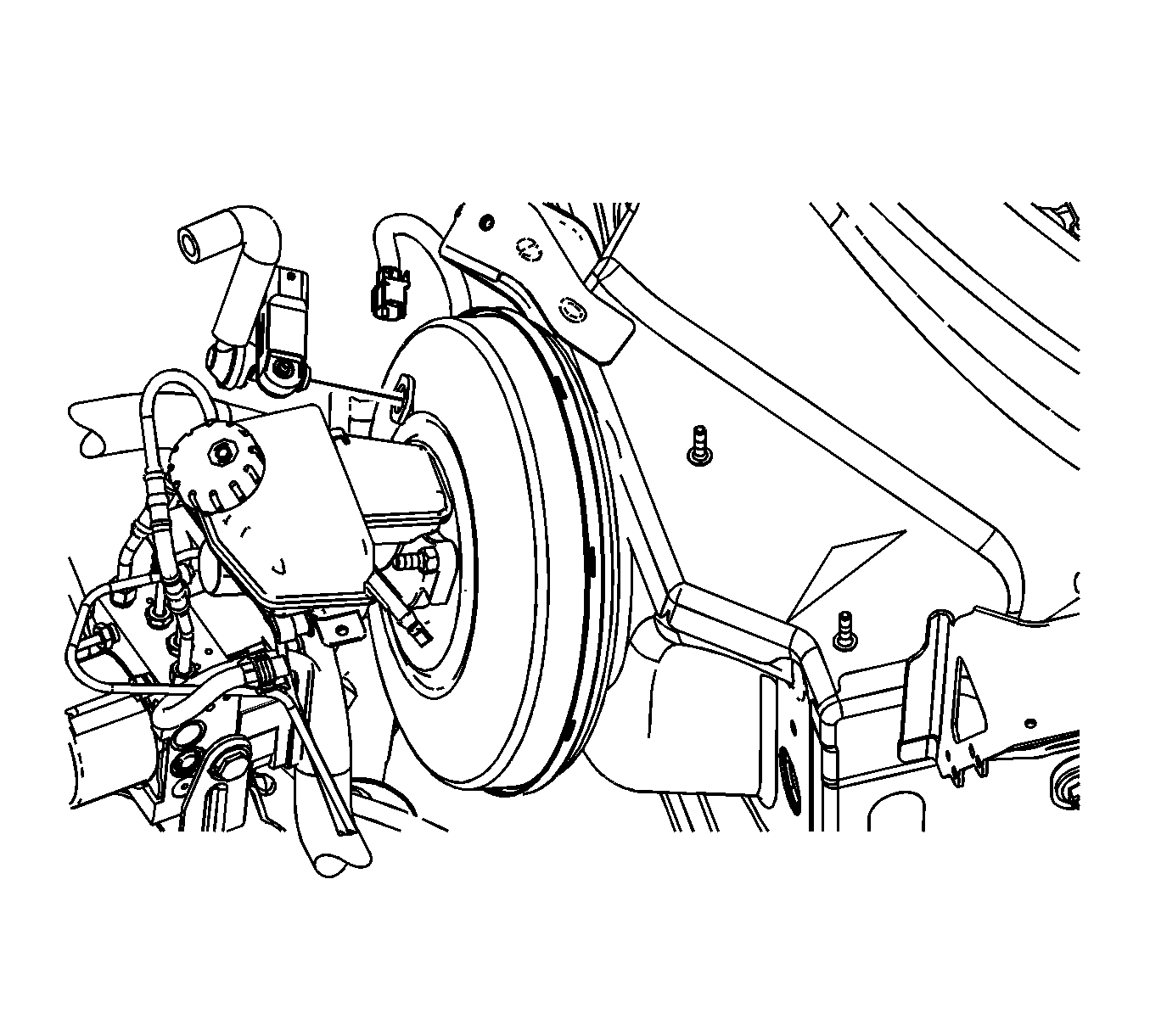
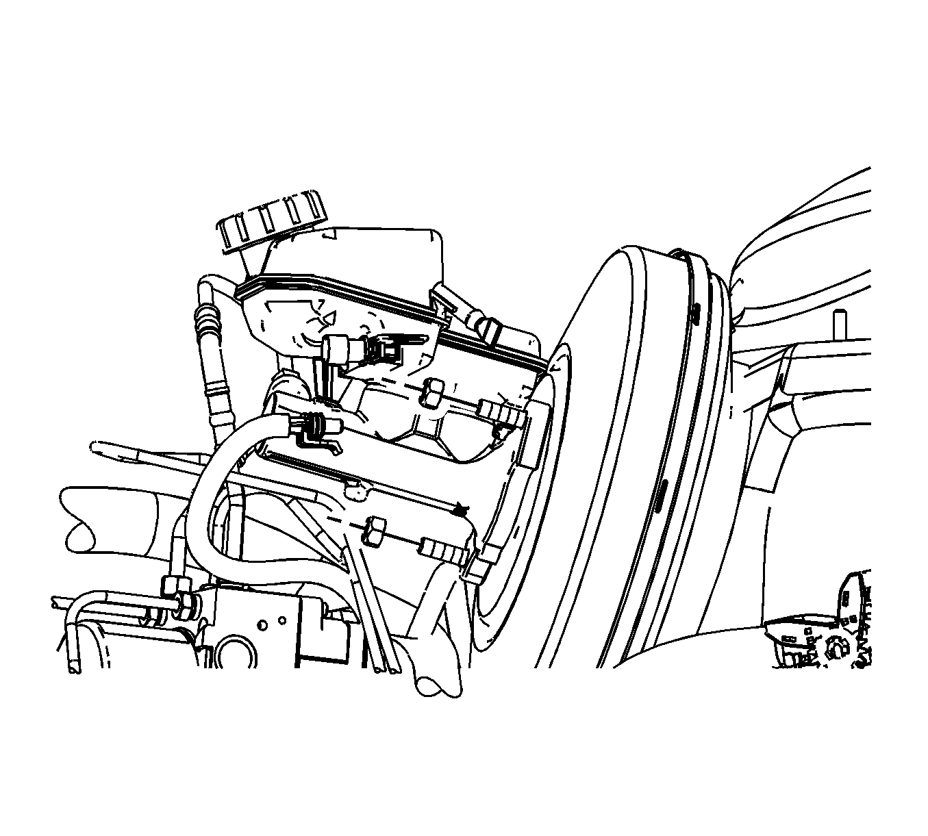
- Clean the electronic brake control module (EBCM) to brake pressure modulator valve (BPMV) area and the brake pipe port areas of any accumulated dirt and foreign material.
- Disconnect the brake fluid level indicator switch electrical connector.
- Disconnect the vacuum brake booster vacuum sensor electrical connector.
- Remove the vacuum brake booster check valve and vacuum sensor assembly from the grommet and position aside.
- Release the wiring harness retainer from the master cylinder mounting stud and position the wiring harness downward.
- Remove and discard the 2 master cylinder nuts.
- Remove the 2 master cylinder brake pipe fittings from the BPMV.
- Remove the brake master cylinder and master cylinder brake pipes as an assembly.
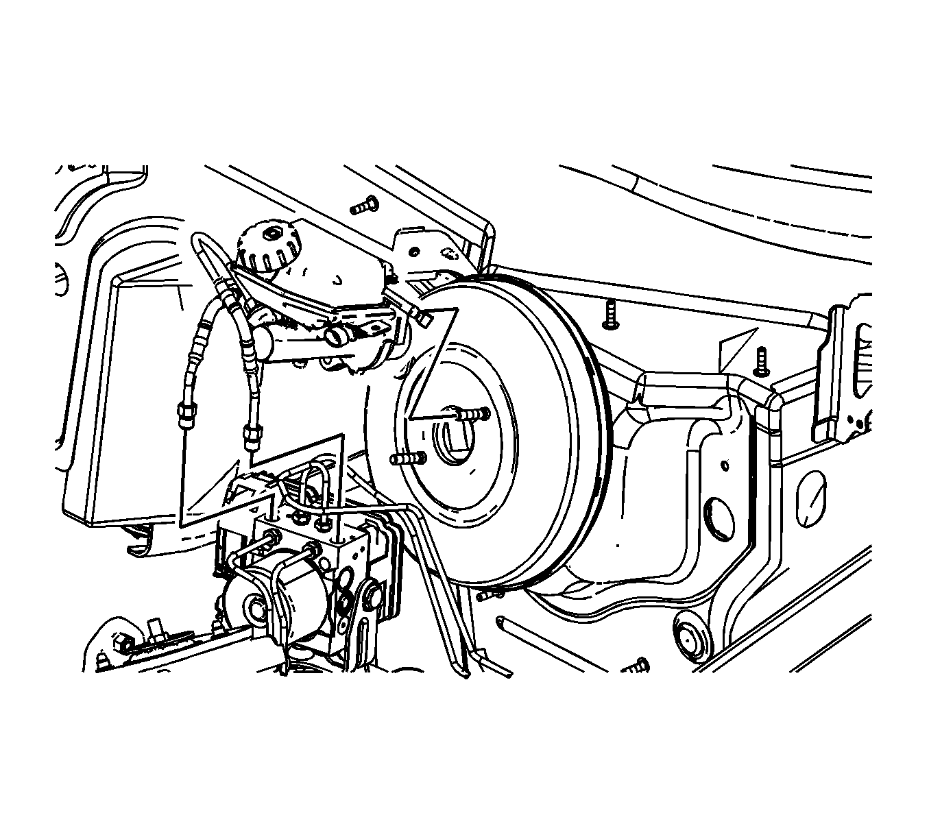
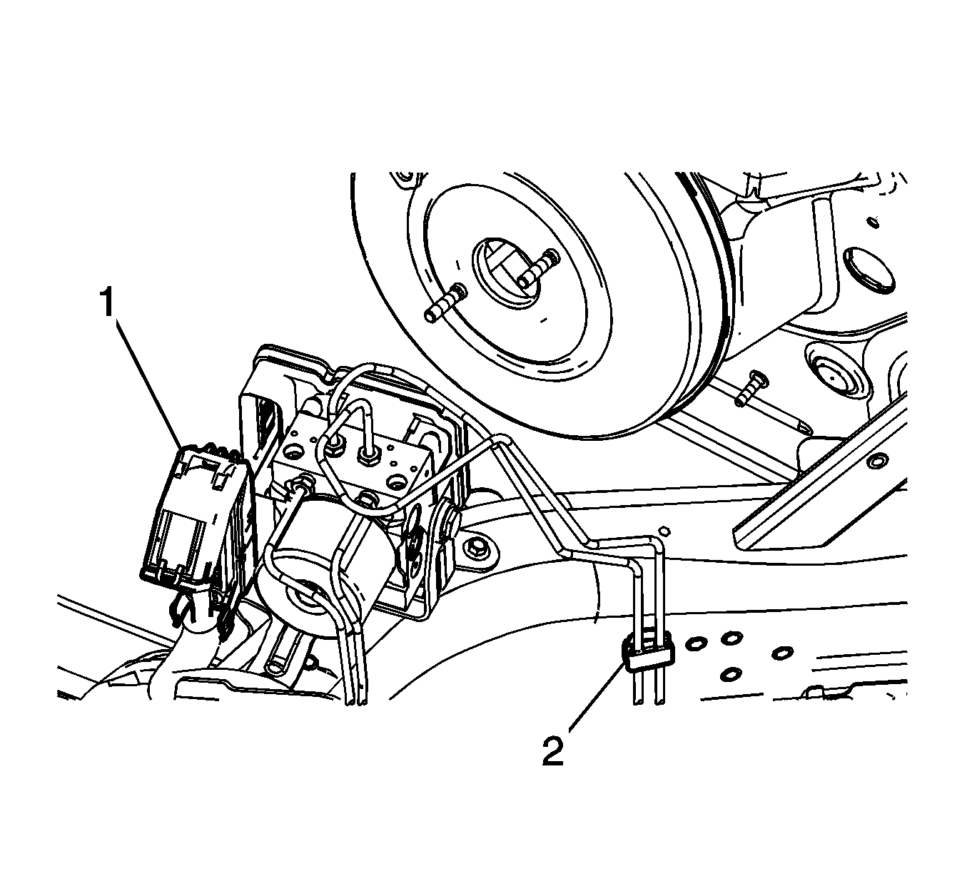
- Lift the locking tabs on the lower edge of the EBCM electrical connector (1) and disconnect the electrical connector.
- Position the EBCM electrical connector and the wiring harness toward the front of the vehicle.
- Release the rear brake pipes retainer (2) from the outboard side of the frame rail.
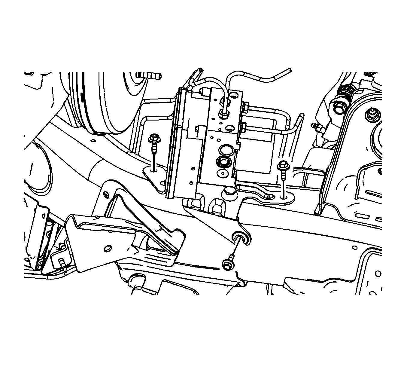
- Remove the 3 BPMV bracket bolts.
- Carefully position the brake modulator assembly forward slightly.
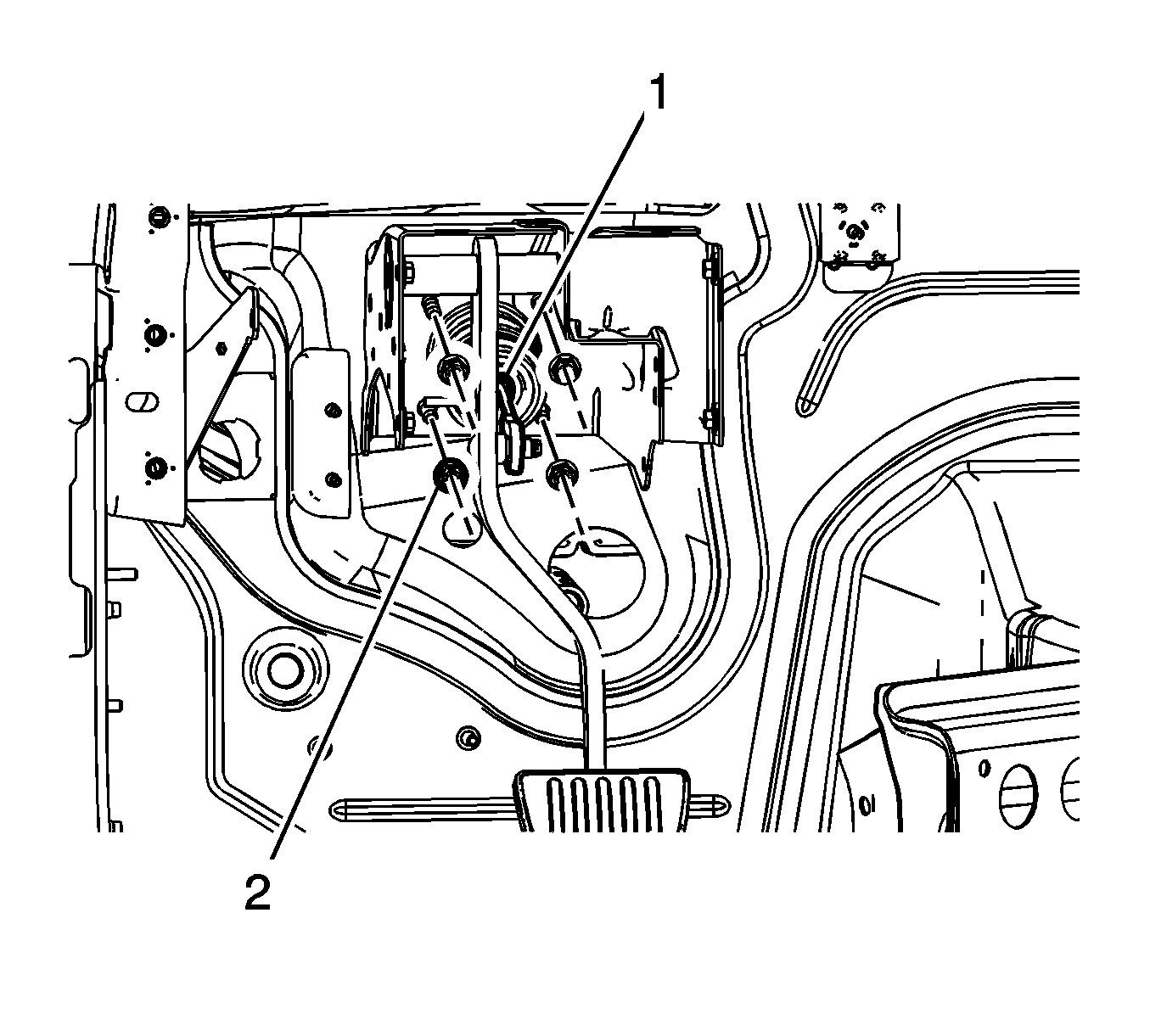
- Remove the power brake booster pushrod nut (1).
- Disconnect the vacuum brake booster pushrod (1) from the brake booster pushrod pin.
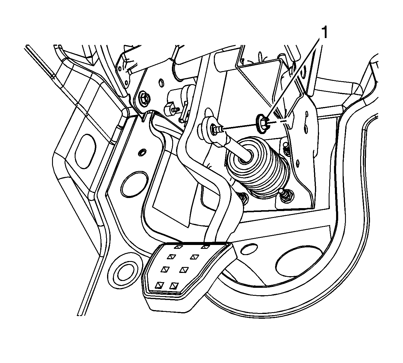
- Remove the 4 vacuum brake booster mounting nuts (2).
- Remove the vacuum brake booster from the vehicle.
Cap the brake pipe fittings and plug the BPMV inlet ports to prevent brake fluid loss and contamination.
Installation Procedure
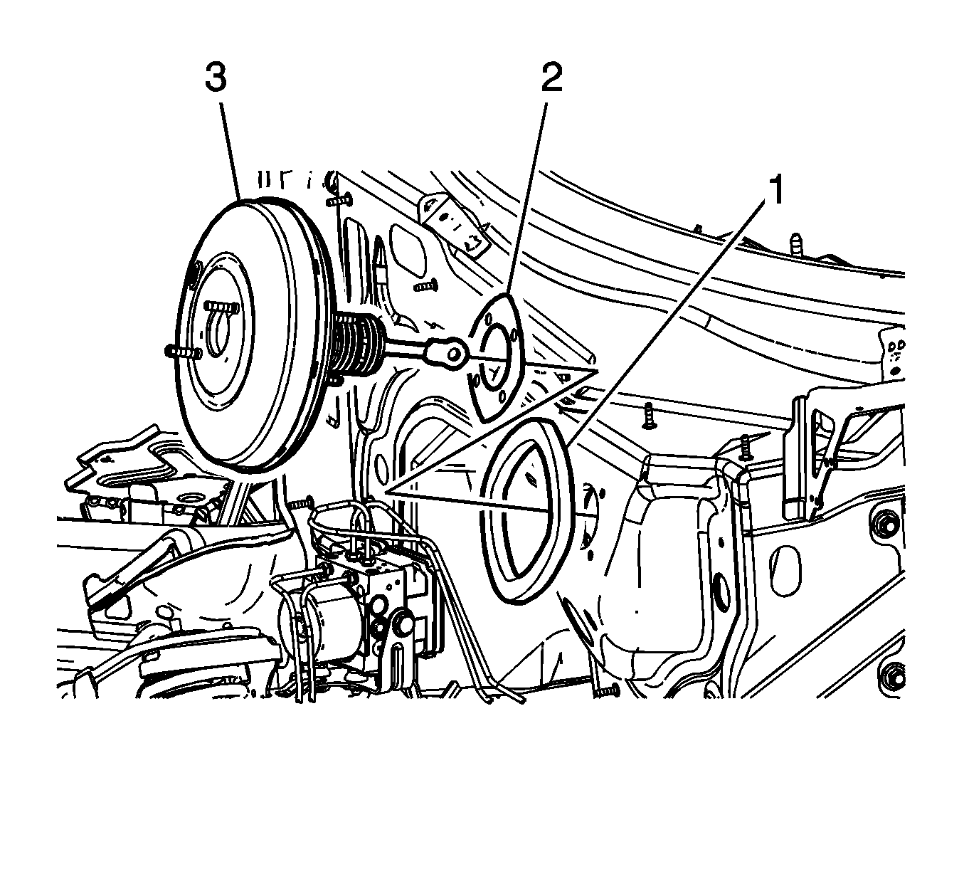
- Inspect the vacuum brake booster to dash panel seal (1) for damage and replace, if necessary.
- Inspect the vacuum brake booster to dash panel gasket (2) for damage and replace, if necessary.
- Install the vacuum brake booster (3) to the vehicle.
- Apply a thin coat of high-temperature grease GM P/N 12345996 (Canadian P/N 10953501) to the brake pedal pivot bushing, the pushrod washer, the push rod pin on the pedal, and the brake pedal pivot pin.
- Connect the vacuum brake booster pushrod (1) to the brake pedal pushrod pin.
- Install the 4 vacuum brake booster mounting nuts (2) and tighten to 25 N·m (18 lb ft).
- Install the power brake booster pushrod nut (1) and tighten to 10 N·m (89 lb in).
- Carefully position the brake modulator assembly to the frame rail.
- Install the 3 BPMV bracket bolts and tighten to 11 N·m (97 lb in)..
- Position the EBCM electrical connector and the wiring harness to the EBCM.
- Connect the EBCM electrical connector (1) . Ensure the tabs on the cam lever are securely locked in place.
- Install the rear brake pipes retainer (2) to the outboard side of the frame rail.
- Install the brake master cylinder and master cylinder brake pipes assembly to the vacuum brake booster.
- Install the master cylinder brake pipe fittings to the BPMV and tighten to 20 N·m (15 lb ft).
- Install 2 new brake master cylinder nuts and tighten to 20 N·m (15 lb ft).
- Position the wiring harness upward and install the wiring harness retainer to the master cylinder mounting stud on the vacuum brake booster.
- Install the vacuum check valve and vacuum sensor assembly to the vacuum brake booster.
- Connect the brake booster vacuum sensor electrical connector.
- Connect the brake fluid level indicator switch electrical connector.
- Bleed the hydraulic brake system. Refer to Hydraulic Brake System Bleeding.
- Calibrate the brake pedal position sensor. Refer to Brake Pedal Position Sensor Calibration.
Caution: Refer to Fastener Caution in the Preface section.
Note: If necessary, a small amount of denatured alcohol can be used as an assembly aid for installing the check valve to the vacuum brake booster grommet. Do not use soap.
