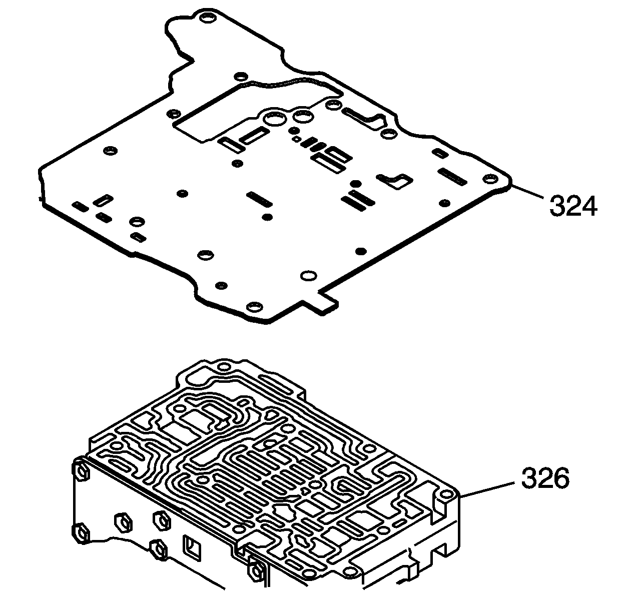
- Install the new spacer plate and gasket assembly (324) onto the rear control valve body assembly (326).
- Install the rear control valve body assembly (326) onto the middle control valve body assembly (323).
- Install 2 - M5 x 0.8 x 35 mm rear control valve body bolts (335).
- Install 1 - M5 x 0.8 x 40 mm rear control valve body bolt (333).
- Hand tighten the 3 rear control valve body assembly bolts (333, 335).
- Install the spacer plate (328) and the 2 new gaskets (327, 329) onto the No. 2 rear control valve body assembly (330).
- Install the No. 2 rear control valve body assembly (330) onto the rear control valve body assembly (326).
- Install 1 - M5 x 0.8 x 76 mm control valve body bolt (331) into the No. 2 rear control valve body assembly.
- Install 4 - M5 x 0.8 x 49.5 mm control valve body bolts (332) into the No. 2 rear control valve body assembly.
- Hand tighten the 5 control valve body assembly bolts (331, 332).
- Turn the valve body assembly over.
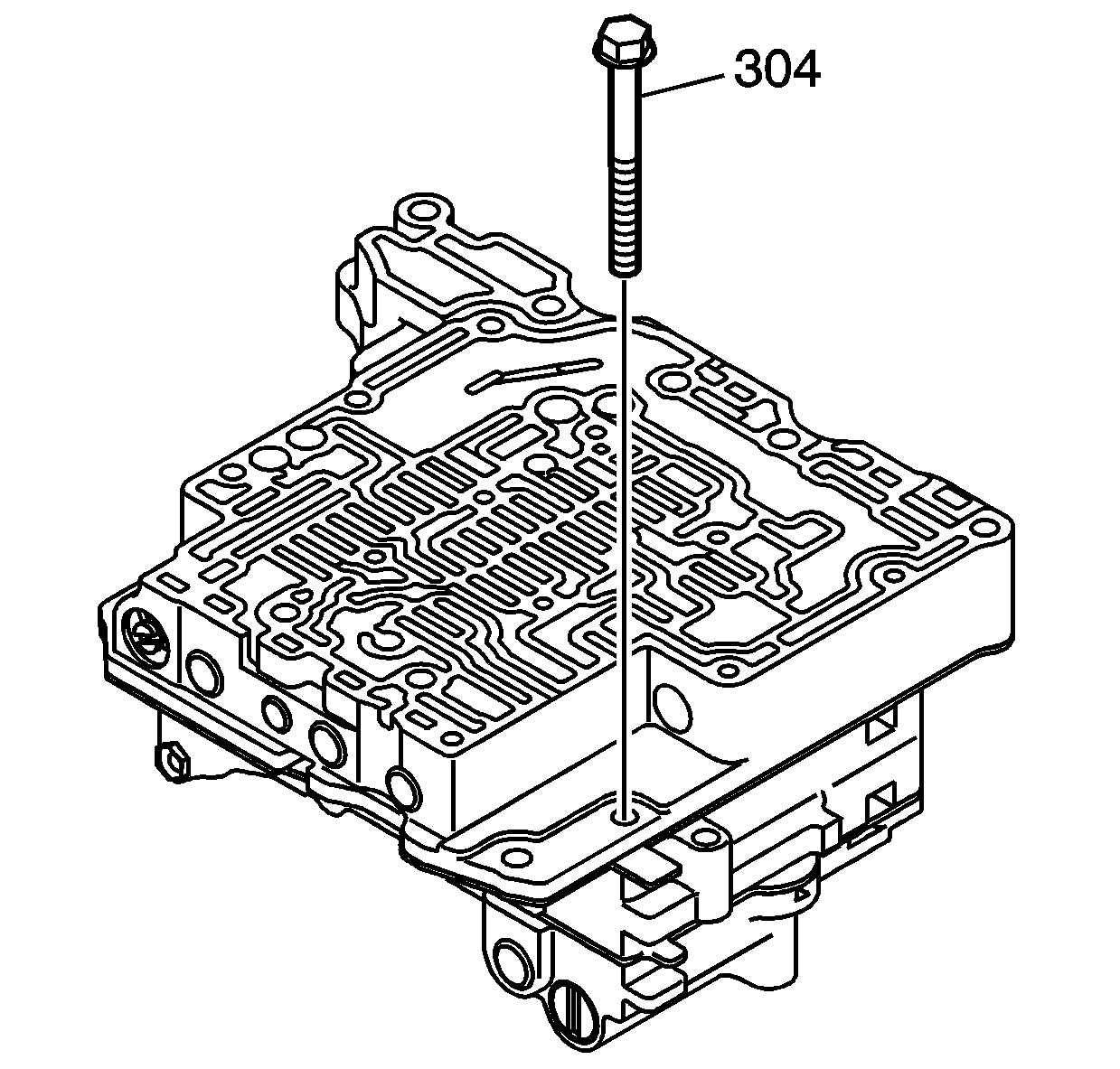
- Install the M5 x 0.8 x 50 mm control valve body bolt (304) and hand tighten.
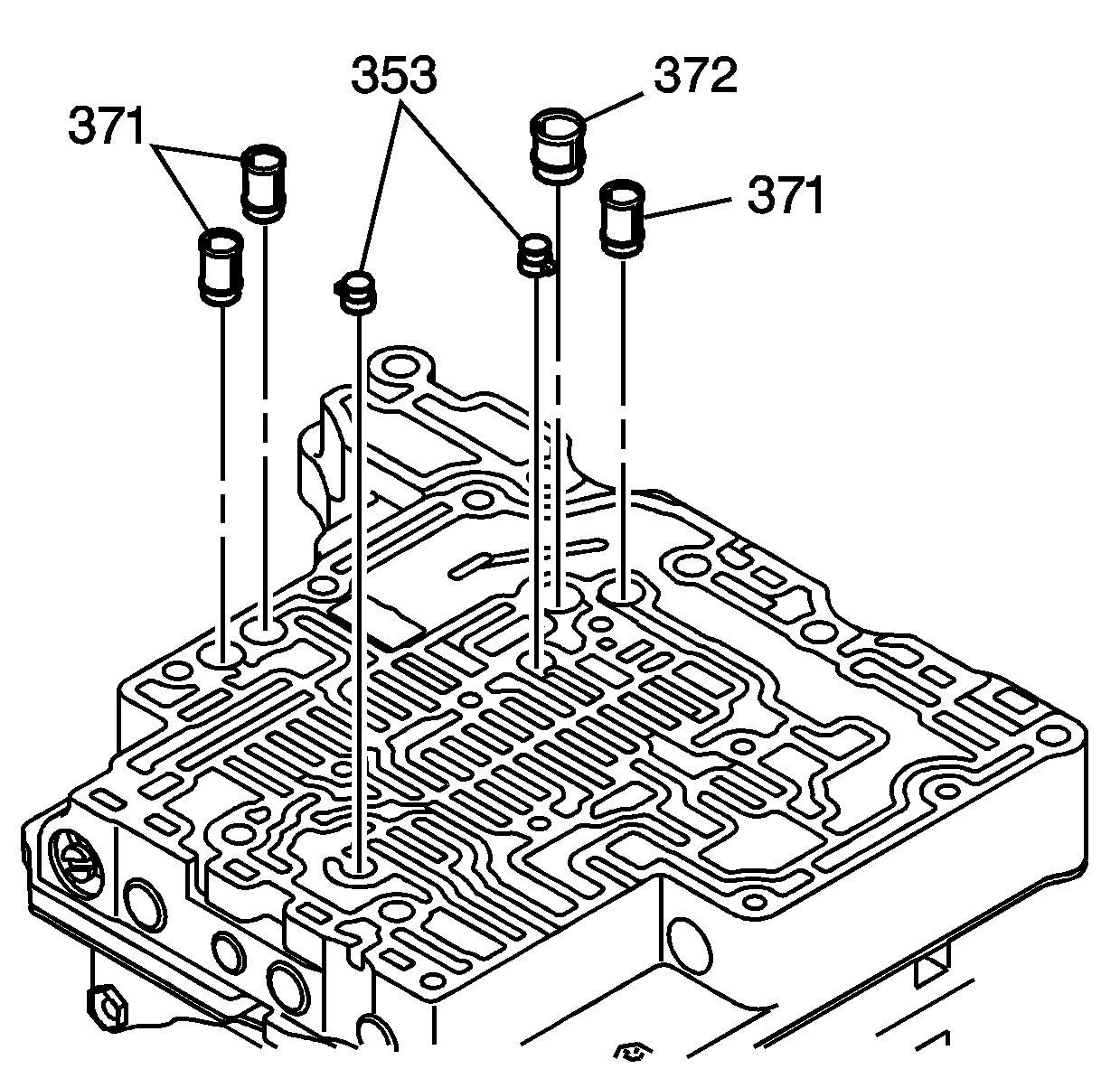
- Install the 3 fluid strainers (371), 1 fluid strainer (372), and the 2 accumulator check valve assemblies (353) into the middle control valve body assembly.
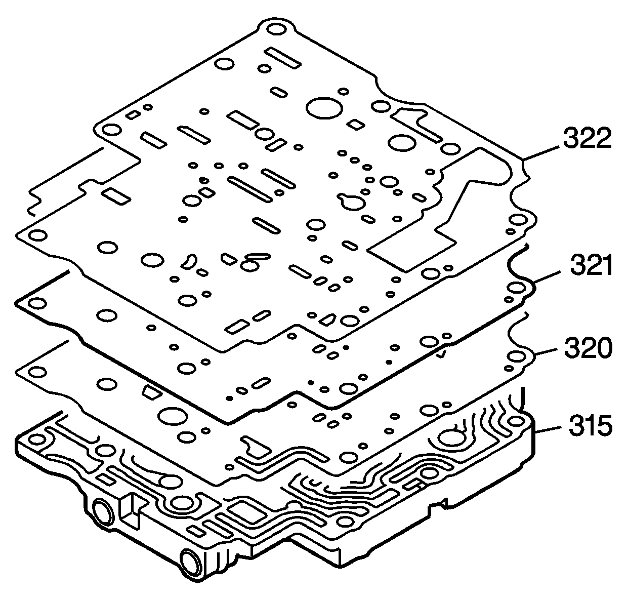
- Install the gasket (320) to the front control valve body assembly (315).
- Install the front control valve body spacer plate (321).
- Install the gasket (322).
- Install the spacer plate and gaskets on to the front control valve body assembly (315).
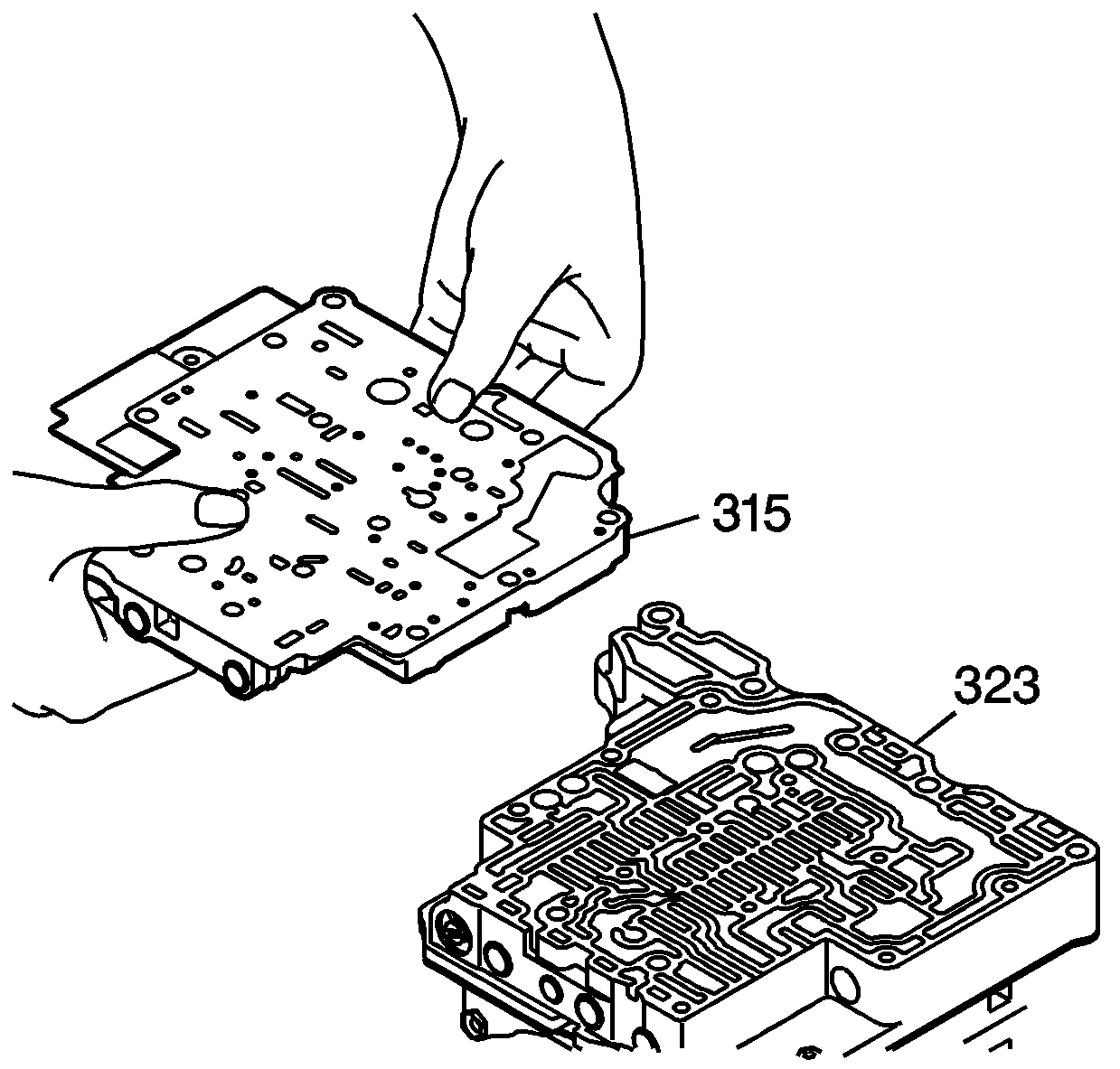
- Install the front control valve body assembly (315) onto the middle control valve body assembly (323).
- Install 1 - M5 x 0.8 x 50 mm control valve body bolt (304) into the front control valve body assembly and hand tighten.
- Install 4 or 5- M5 x 0.8 x 20 mm control valve body bolts (313) into the front control valve body assembly and hand tighten.
- Install 2 - M5 x 0.8 x 16 mm control valve body bolts (314) into the front control valve body assembly and hand tighten.
- Tighten all 16 control valve body assembly bolts, evenly and gradually. Tighten the control valve body assembly bolts to 7 N·m (62 lb in) .
- Replace the O-ring seals (306) on each of the 5 shift solenoid valves (300, 303, 305, 308, 310).
- Install the 5 shift solenoid valves (300, 303, 305, 308, 310).
- Install the 5 shift solenoid valve retaining bolts.
- Tighten the 5 shift solenoid valve retaining bolts (301, 302, 307). Tighten the shift solenoid valve retaining bolts to 7 N·m (62 lb in) .
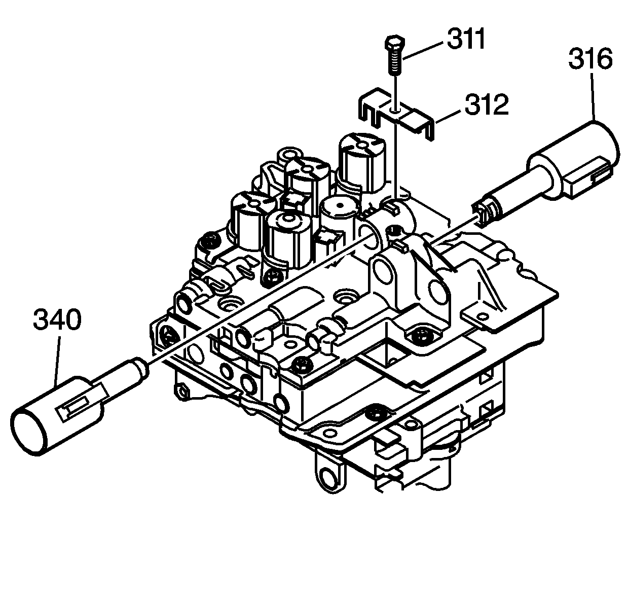
- Install the line pressure control solenoid valve assembly (316) and the shift pressure control solenoid valve assembly (340).
- Install the control valve body solenoid valve retainer (312) and 1 - M5 x 0.8 x 13 mm control valve body bolt (311). Tighten the control valve body bolt to 7 N·m (62 lb in) .
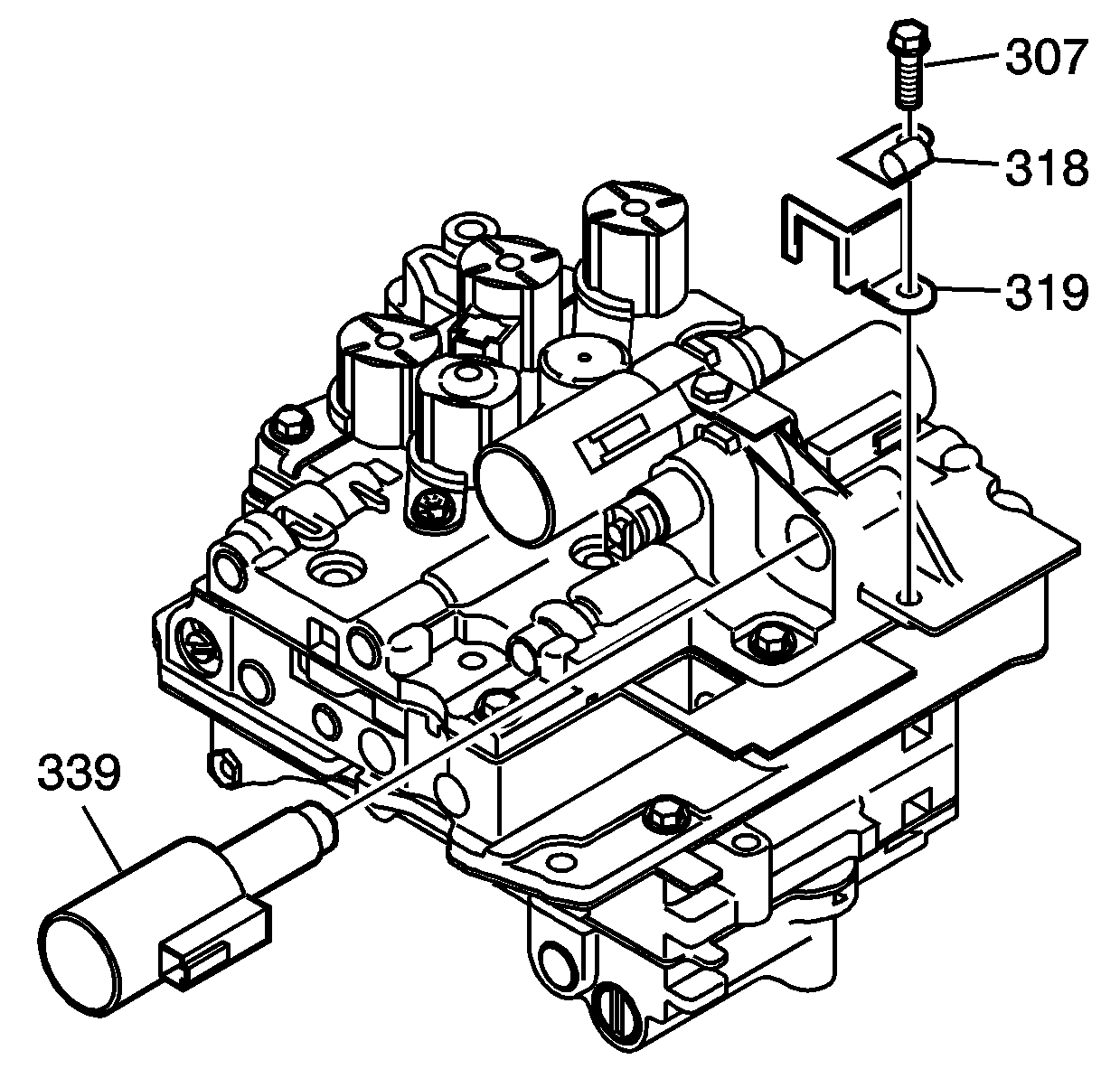
- Install the TCC lock up pressure control solenoid valve assembly (339).
- Install the TCC lock up pressure control solenoid valve retainer (319), the wiring harness clip (318), and 1 - M5 x 0.8 x 10 mm control valve body bolt/screw (307). Tighten the control valve body bolt to 7 N·m (62 lb in) .
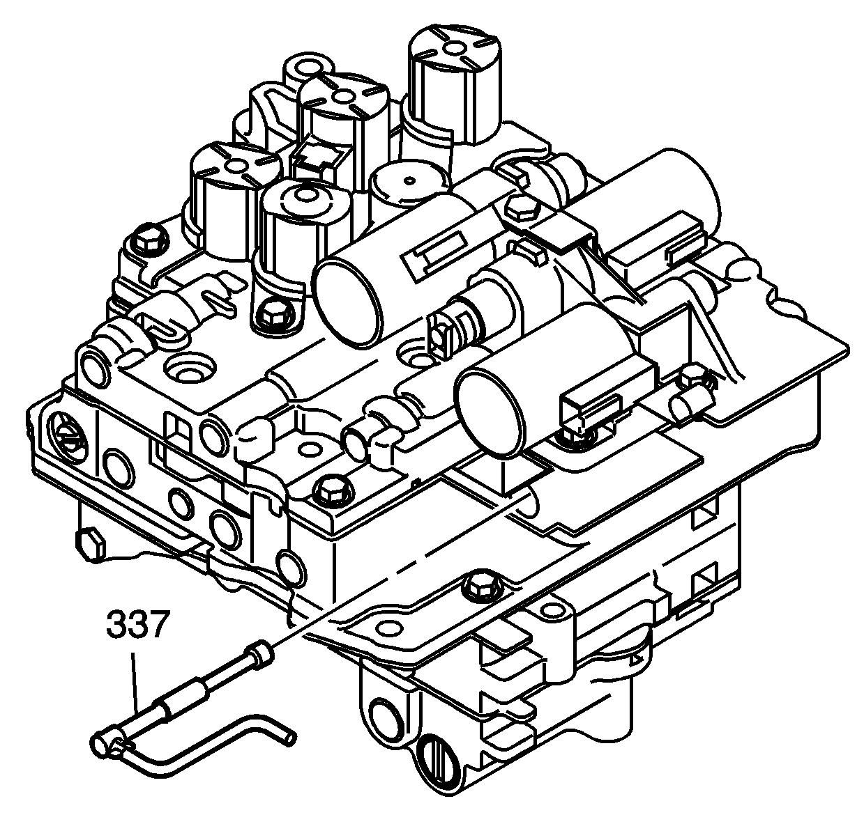
- Install the manual valve (337) into the middle control valve body assembly.
Note: Align each bolt hole in the valve body with the holes in the spacer plate and gasket assembly.
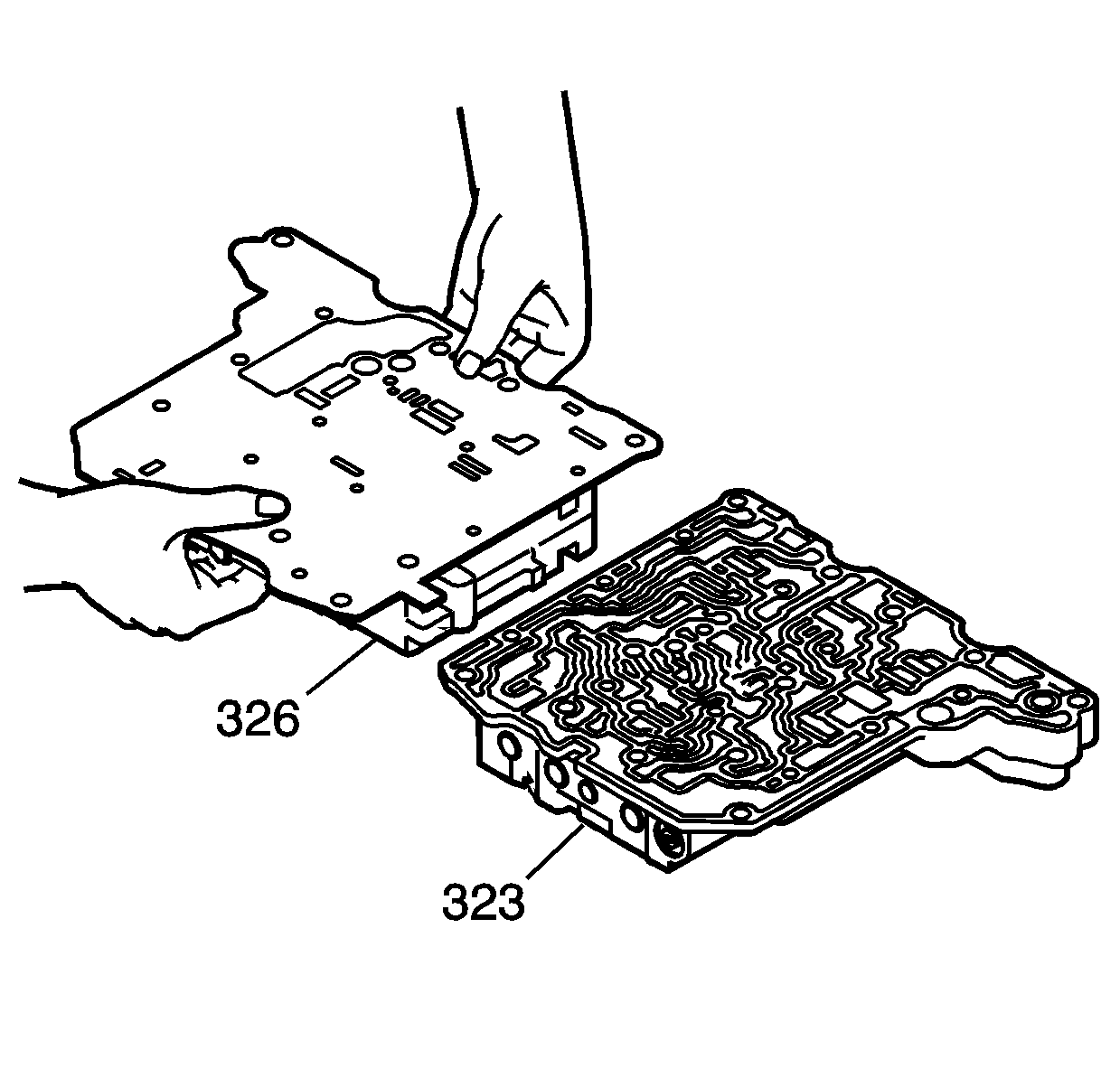
Note: Align each bolt hole in the valve body with the holes in the spacer plate and gasket assembly.
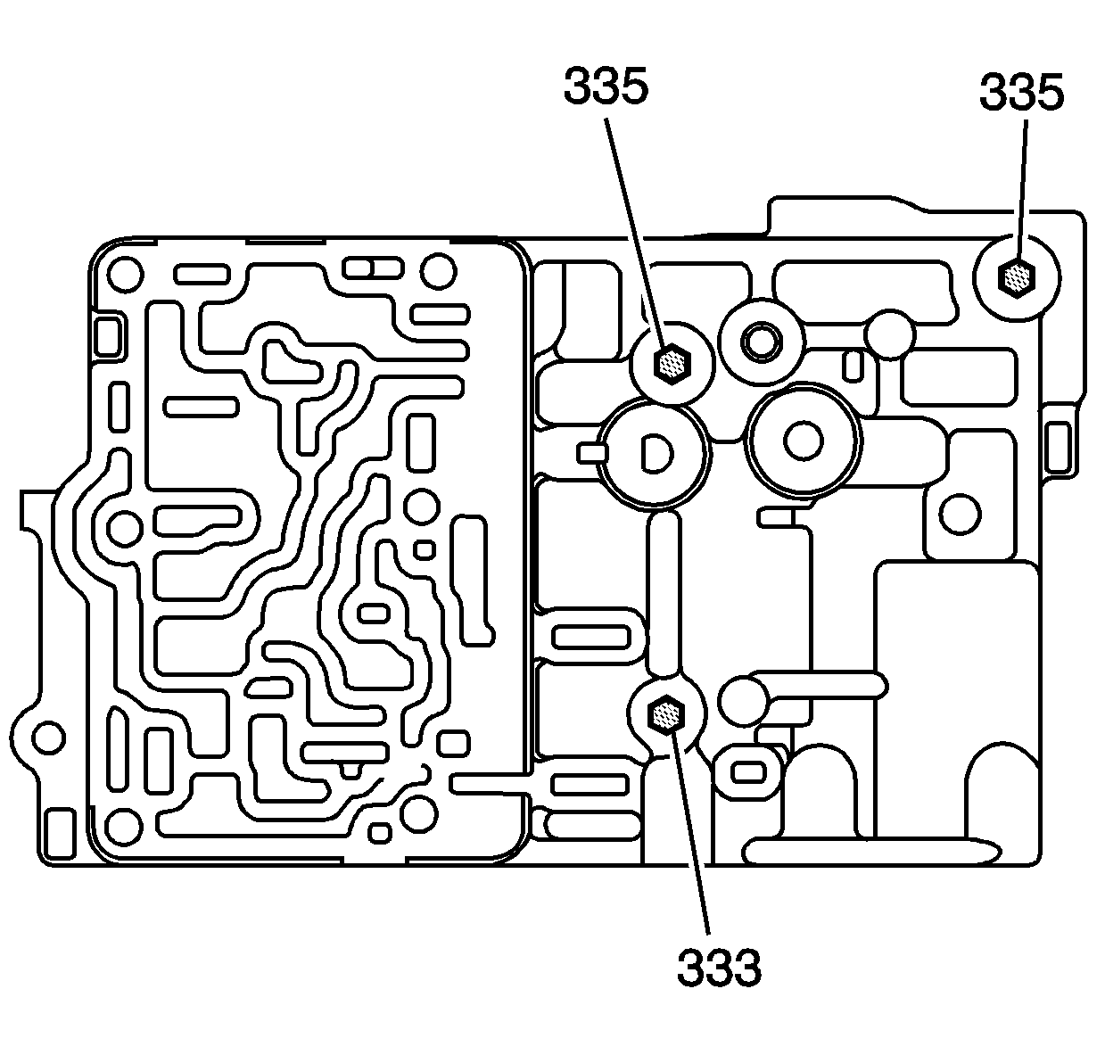
Caution: Use the correct fastener in the correct location. Replacement fasteners must be the correct part number for that application. Fasteners requiring replacement or fasteners requiring the use of thread locking compound or sealant are identified in the service procedure. Do not use paints, lubricants, or corrosion inhibitors on fasteners or fastener joint surfaces unless specified. These coatings affect fastener torque and joint clamping force and may damage the fastener. Use the correct tightening sequence and specifications when installing fasteners in order to avoid damage to parts and systems.
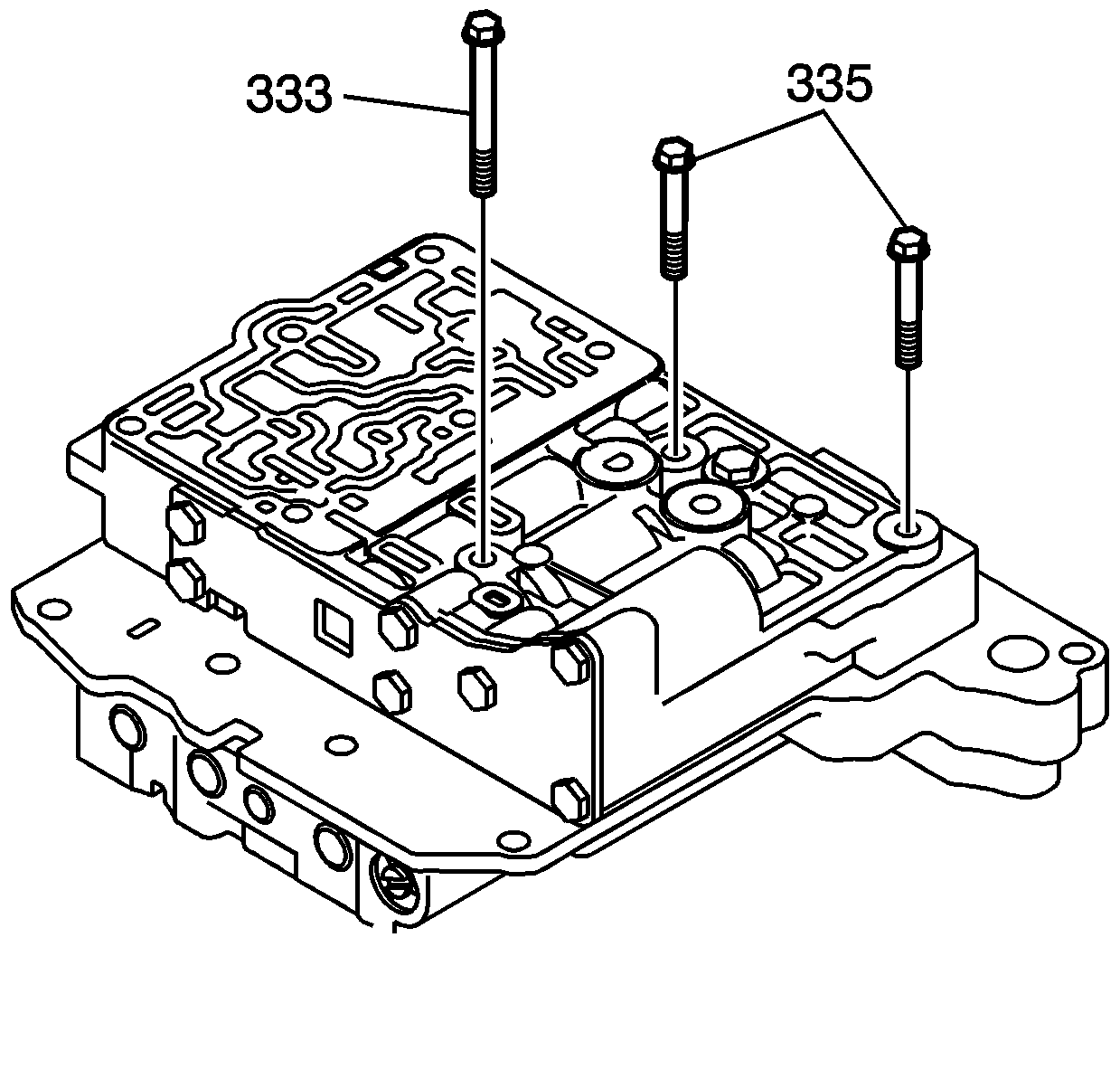
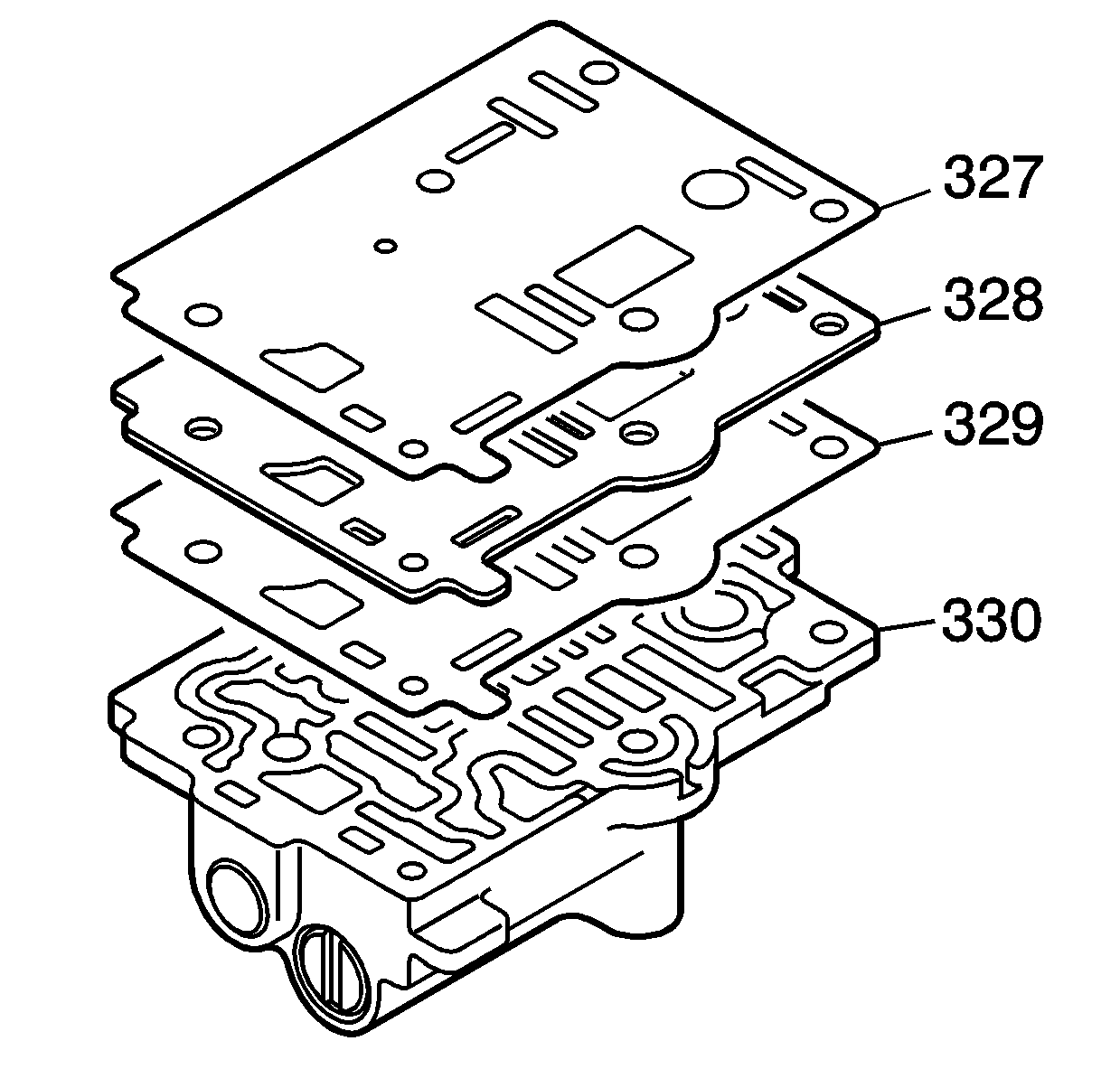
Note: Align each bolt hole on the valve body with the holes in the gaskets and plates.
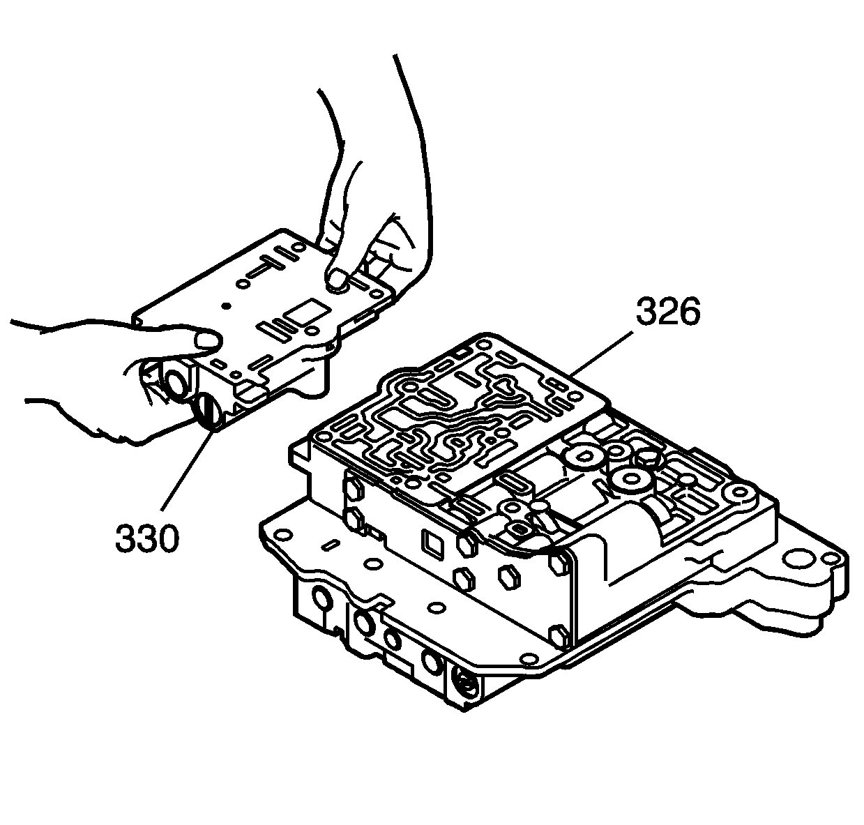
Note: Align each bolt hole on the valve body with the holes in the gaskets and plates.
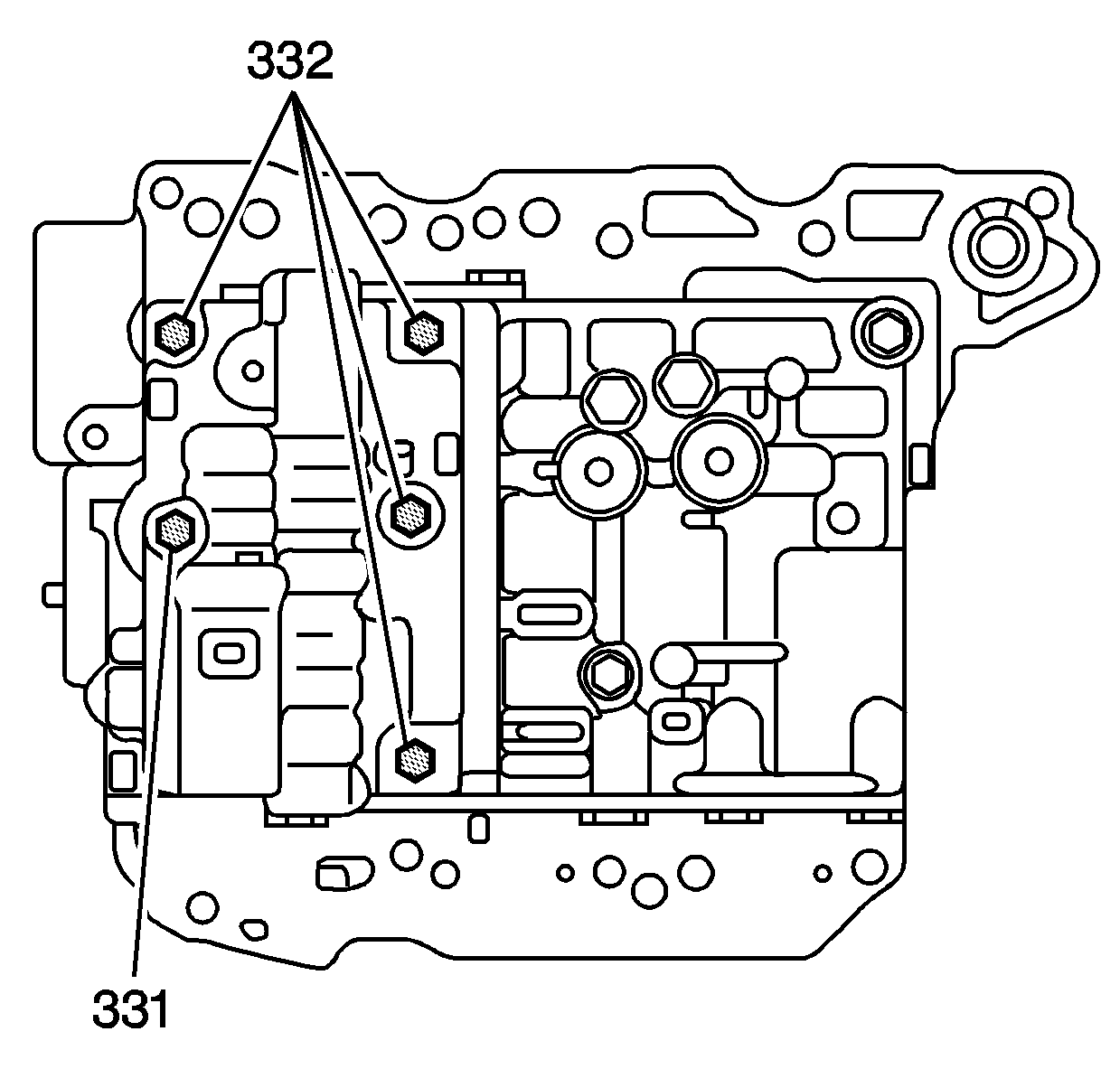
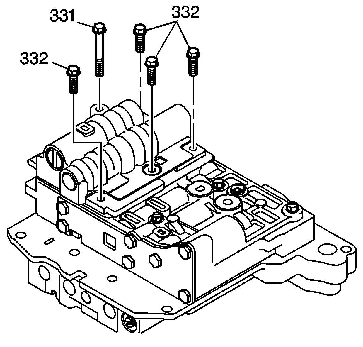
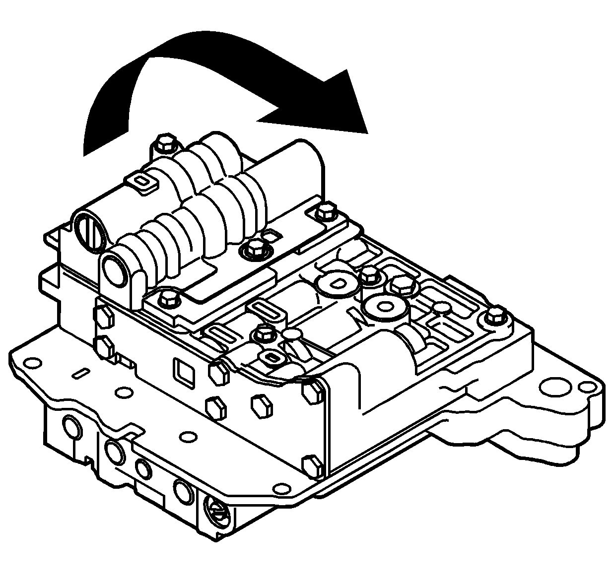
Note: Align each bolt hole in the valve body with the holes in the gaskets and spacer plate.
Note: Align each bolt hole in the valve body with the holes in the gaskets and spacer plate.
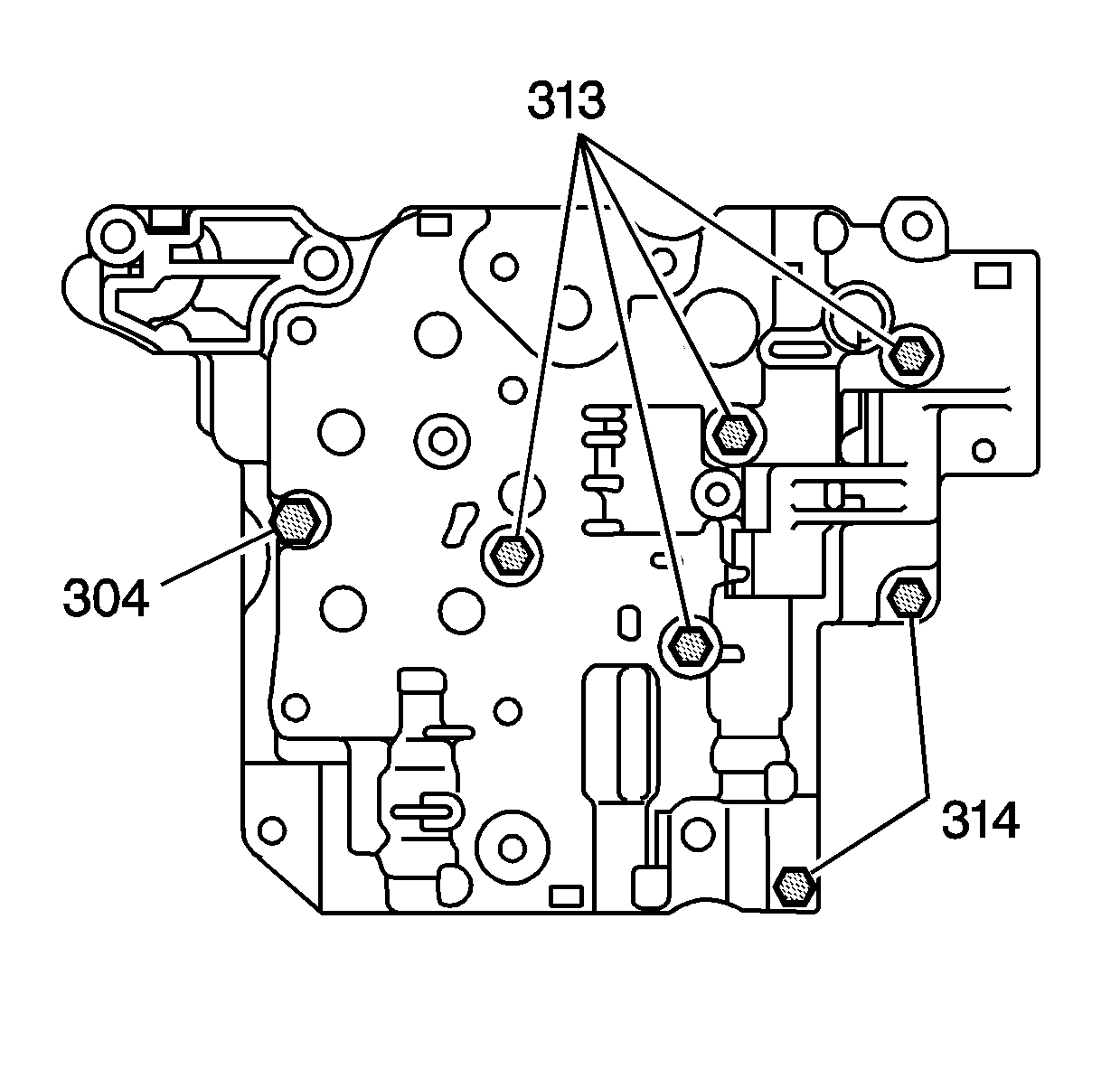
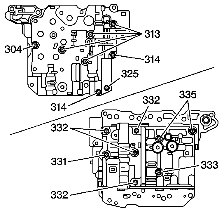
Caution: Use the correct fastener in the correct location. Replacement fasteners must be the correct part number for that application. Fasteners requiring replacement or fasteners requiring the use of thread locking compound or sealant are identified in the service procedure. Do not use paints, lubricants, or corrosion inhibitors on fasteners or fastener joint surfaces unless specified. These coatings affect fastener torque and joint clamping force and may damage the fastener. Use the correct tightening sequence and specifications when installing fasteners in order to avoid damage to parts and systems.
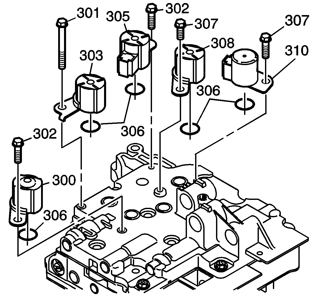
Note:
• Use NEW O-ring seals. • Do not damage the O-ring seals.
| • | 1 - (301) - M5 x 0.8 x 62 mm |
| • | 2 - (302) - M5 x 0.8 x 28 mm |
| • | 2 - (307) - M5 x 0.8 x 10 mm |
