Transmission Control Module (TCM) (75)
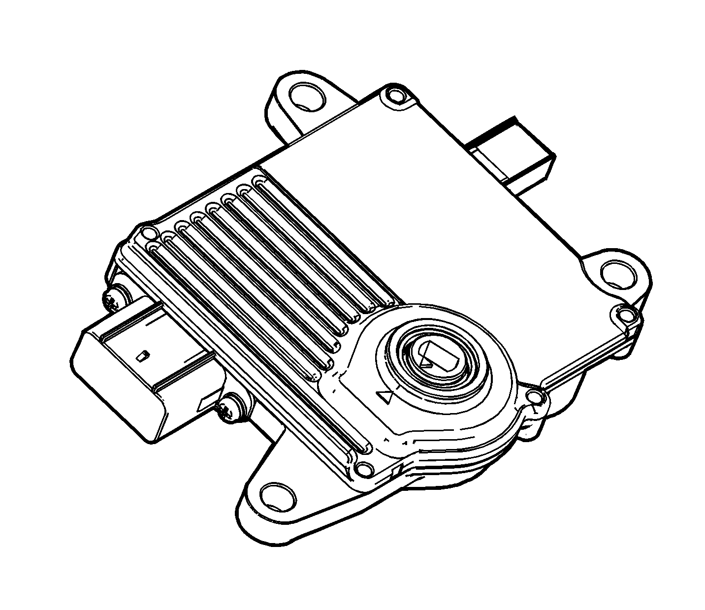
The transmission control module (TCM) primarily controls shift points and lockup engagement.
The transmission is controlled by an electronic shift system. The TCM processes input signals. From the information received, the TCM controls the transmission hydraulic system.
The electronic shift system consists of the following components:
| • | Transmission Control Module (TCM) |
| • | Shift Solenoid (SS1 and SS2) |
| • | Pressure Control Solenoid (PSC) |
| • | Lockup Solenoid |
| • | Input Shaft Speed (ISS) Sensor |
| • | Output Shaft Speed (OSS) Sensor |
| • | Transmission Fluid Temperature (TFT) Sensor |
| • | Transmission Range (TR) Switch |
Automatic Transmission Input Speed (A/T ISS) Sensor Assembly (73)
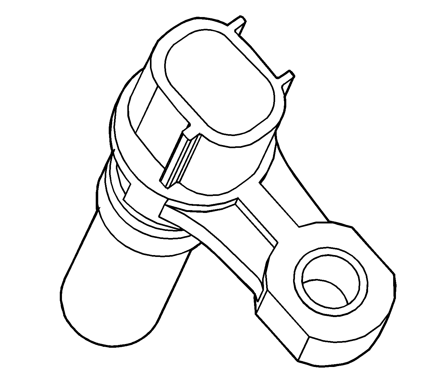
The A/T ISS sensor operates identically to the A/T OSS sensor except it uses the stamped teeth on the forward and direct clutch housing assembly - with input shaft as the rotor (reluctor). Remember that the forward and direct clutch housing assembly - with input shaft is driven at converter turbine speed. The A/T ISS sensor square wave form is also compared to a fixed clock signal internally within the TCM to determine actual converter turbine speed. The TCM uses transmission input and output speeds to help determine line pressure, transmission shift patterns, TCC apply pressure, gear ratios, and TCC slippage for diagnostic purposes.
Shift Solenoid Valves
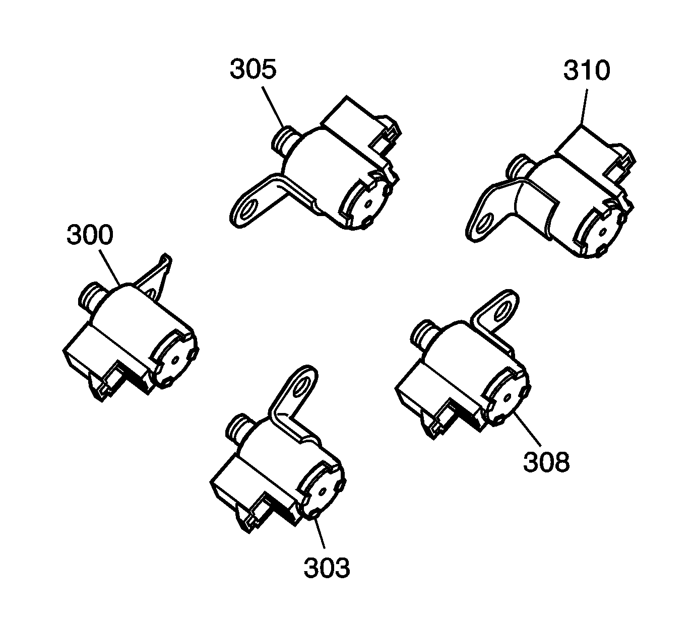
The AF33-5 uses five electromagnetic shift solenoid valves to control upshifts and downshifts in all forward gear ranges. These shift solenoid valves are controlled by the TCM and work together in a combination of ON and OFF sequences to control the various shift valves. The TCM uses numerous inputs to determine which solenoid state combination the transmission should be in. The following table shows the solenoid state combination required for each gear range. Refer to Shift Solenoid Valve State and Gear Ratio .
Normally Open Shift Solenoid Valves
Three of the shift solenoid valves used in the AF33-5 (the reverse, 1st SS valve; the 2-3, 3-4 SS valve; and the 3-4, 4-5 SS valve) are referred to as normally open solenoid valves. Normally open shift solenoid valves are de-energized (turned OFF) when the TCM opens the path to ground for the solenoid's electrical circuit. With the solenoid OFF, signal fluid moves the metering ball and plunger away from the exhaust seat. This allows signal fluid to flow past the metering ball and exhaust through the solenoid. As a result of this exhaust, there is no pressure in the signal fluid circuit when the normally open solenoid is OFF. When the TCM provides a path to ground for the electrical circuit to energize (turn ON) the solenoid, current flows through the coil assembly in the solenoid and creates a magnetic field. The magnetic field moves the plunger inside the solenoid and seats the metering ball against the exhaust seat, thereby blocking the exhaust passage and causing signal fluid pressure to increase.
Normally Closed Shift Solenoid Valves
The remaining two shift solenoid valves used in the AF33-5 (the 1-2, 2-3, reverse SS valve and the reverse SS valve) are referred to as normally closed solenoid valves. Normally closed shift solenoid valves function similar to normally open shift solenoid valves in that the TCM controls the path to ground for the electrical circuit to turn the solenoid ON or OFF. The normally closed shift solenoid valves are de-energized (turned OFF) when the TCM opens the path to ground for the solenoid's electrical circuit. However, when a normally closed solenoid is OFF, spring pressure seats the plunger and metering ball against the exhaust seat, thereby blocking the exhaust passage and causing signal fluid pressure to increase. When the TCM provides a path to ground for the electrical circuit to energize (turn ON) the solenoid, current flows through the coil assembly in the solenoid and creates a magnetic field. The magnetic field moves the plunger against spring force and moves the metering ball away from the exhaust seat. This allows signal fluid to flow past the metering ball and exhaust through the solenoid. As a result of this exhaust, there is no pressure in the signal fluid circuit when the normally closed solenoid is ON.
Line Pressure Control Solenoid Valve (SLT) (316)
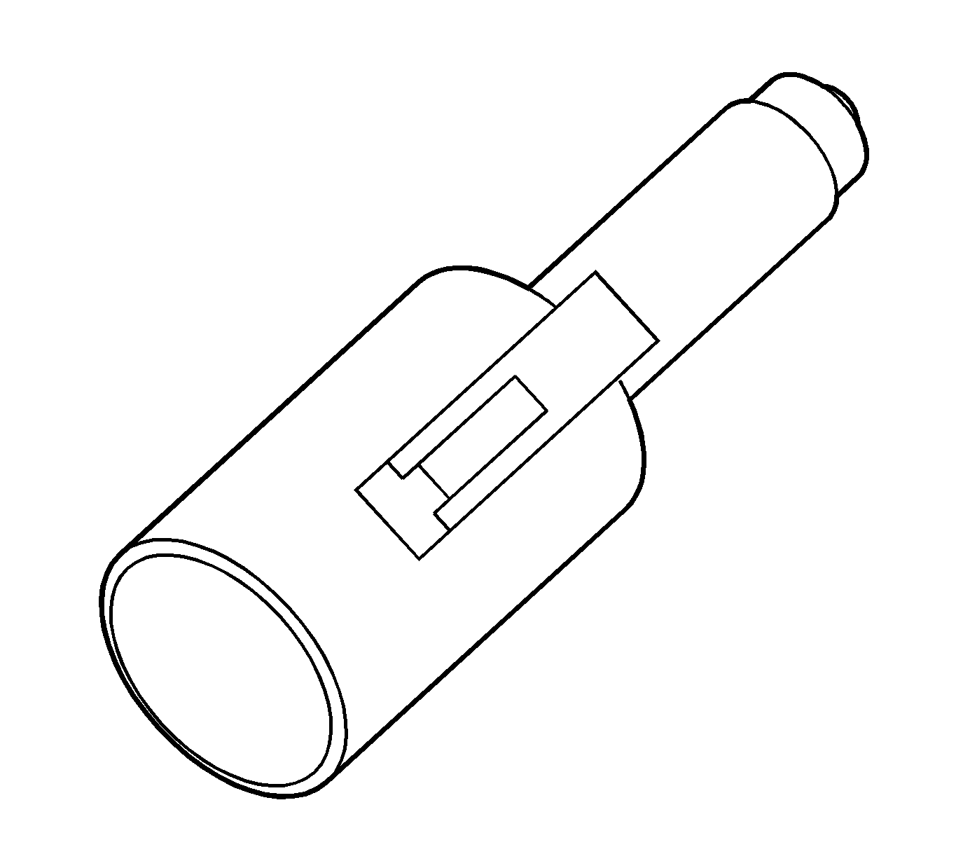
The line pressure control solenoid valve (normally high, 3-port linear pressure control solenoid) is a precision electronic pressure regulator that controls transmission line pressure based on current flow through its coil windings. As current flow is increased, the magnetic field produced by the coil moves the solenoid's plunger further away from the exhaust port. Opening the exhaust port decreases the output fluid pressure regulated by the line pressure control solenoid valve, which ultimately decreases line pressure. The TCM controls the line pressure control solenoid valve based on various inputs including throttle position, transmission fluid temperature and gear state.
Duty Cycle, Frequency and Current Flow
A "duty cycle" may be defined as the percentage of time current is flowing through a solenoid coil during each cycle. The number of cycles that occur within a specified amount of time, usually measured in seconds, is called "frequency". Typically, the operation of an electronically controlled pulse width modulated solenoid is explained in terms of duty cycle and frequency.
The TCM controls the line pressure control solenoid valve on a positive duty cycle at a fixed frequency of 292.5 Hz (cycles-per-second). A higher duty cycle provides a greater current flow through the solenoid. The high (positive) side of the line pressure control solenoid valve electrical circuit at the TCM controls the line pressure control solenoid valve operation. The TCM provides a ground path for the circuit, monitors average current and continuously varies the line pressure control solenoid valve duty cycle to maintain the correct average current flowing through the line pressure control solenoid valve.
Duty Cycle | Current | Line Pressure |
|---|---|---|
Minimum | 0.1 amps | Maximum |
Maximum | 1.1 amps | Minimum |
Line pressure control solenoid valve resistance should measure between 5.0 and 5.6 ohms when measured at 20°C (68°F).
The duty cycle and current flow to the line pressure control solenoid valve are mainly affected by throttle position (engine torque) and they are inversely proportional to throttle angle (engine torque). In other words, as the throttle angle (engine torque) increases, the duty cycle is decreased by the TCM which decreases current flow to the line pressure control solenoid valve. Current flow to the line pressure control solenoid valve creates a magnetic field that moves the solenoid plunger against spring force.
TCC Lock Up Pressure Control Solenoid Valve (SLU) (339)
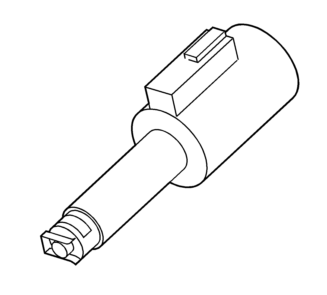
The TCC lock up pressure control solenoid valve is a normally low, 3-port linear pressure control solenoid used to control the apply and release of the 2nd (B2) and low and reverse (B3) clutches, and the torque converter clutch. The TCM operates the solenoid with a negative duty cycle at a fixed frequency of 32 Hz to control the rate of clutch apply/release. The solenoid's ability to "ramp" the clutch apply and release pressures results in a smoother clutch operation.
When vehicle operating conditions are appropriate to apply the TCC, the TCM increases the duty cycle to allow the TCC lock up pressure control solenoid valve to command lock up control and TCC signal fluid pressure at a level sufficient to move the lock up relay valve and the lock up control valve to the apply position. Release fluid pressure is directed to exhaust, and apply) fluid is directed to the apply side of the converter pressure plate/damper assembly. The TCM then increases the duty cycle to control a slippage of 20-80 RPM between the pressure plate/damper assembly and the converter cover. This provides for improved filtration of engine vibrations and allows the TCC to apply at low engine speeds in 2nd, 3rd, 4th and 5th gear. At high speed, lock up mode is set by activating the TCC lock up pressure control solenoid valve at maximum duty cycle.
Release of the TCC is achieved by decreasing the duty cycle to a level low enough to allow spring force to move the lock up relay valve and the lock up control valve to the release position. Apply fluid is directed to exhaust and converter feed fluid is directed into the release circuit to the release side of the pressure plate/damper assembly.
There are also some operating conditions that may prevent or enable TCC apply under various conditions (engine temperature, transmission temperature, brake switch activation) depending on vehicle application.
TCC lock up pressure control solenoid valve resistance should measure between 5.0 and 5.6 ohms when measured at 20°C (68°F).
Shift Pressure Control Solenoid Valve (SLS) (340)
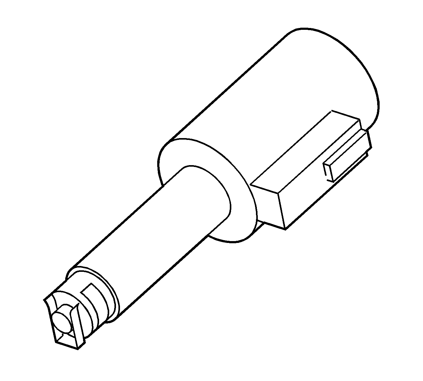
The shift pressure control solenoid valve (normally high, 3-port linear pressure control solenoid) is a precision electronic pressure regulator that controls transmission clutch apply pressure based on current flow through its coil windings. As current flow is increased, the magnetic field produced by the coil moves the solenoid's plunger further away from the exhaust port. Opening the exhaust port decreases the output fluid pressure regulated by the shift pressure control solenoid valve, which ultimately decreases clutch apply pressure. The TCM controls the shift pressure control solenoid valve based on various inputs including throttle position, transmission fluid temperature and gear state.
Duty Cycle, Frequency and Current Flow
A "duty cycle" may be defined as the percentage of time current is flowing through a solenoid coil during each cycle. The number of cycles that occur within a specified amount of time, usually measured in seconds, is called "frequency". Typically, the operation of an electronically controlled pulse width modulated solenoid is explained in terms of duty cycle and frequency.
The TCM controls the shift pressure control solenoid valve on a positive duty cycle at a fixed frequency of 292.5 Hz (cycles-per-second). A higher duty cycle provides a greater current flow through the solenoid. The high (positive) side of the shift pressure control solenoid valve electrical circuit at the TCM controls the shift pressure control solenoid valve operation. The TCM provides a ground path for the circuit, monitors average current and continuously varies the shift pressure control solenoid valve duty cycle to maintain the correct average current flowing through the shift pressure control solenoid valve.
Duty Cycle | Current | Line Pressure |
|---|---|---|
Minimum | 0.1 amps | Maximum |
Maximum | 1.1 amps | Minimum |
Shift pressure control solenoid valve resistance should measure between 5.0 and 5.6 ohms when measured at 20°C (68°F).
The duty cycle and current flow to the shift pressure control solenoid valve are mainly affected by throttle position (engine torque) and they are inversely proportional to throttle angle (engine torque). In other words, as the throttle angle (engine torque) increases, the duty cycle is decreased by the TCM which decreases current flow to the shift pressure control solenoid valve. Current flow to the shift pressure control solenoid valve creates a magnetic field that moves the solenoid plunger against spring force.
Automatic Transmission Fluid Temperature (TFT) Sensor (36)
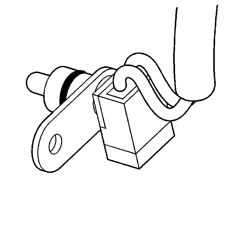
The TFT sensor (36) is part of the automatic transmission wiring harness assembly. The TFT sensor is a resistor, or thermistor, which changes value based on temperature. The sensor has a negative-temperature coefficient. This means that as the temperature increases, the resistance decreases, and as the temperature decreases the resistance increases. The TCM supplies a 5-volt reference signal to the sensor and measures the voltage drop in the circuit. When the transmission fluid is cold the sensor resistance is high and the TCM detects high signal voltage. As the fluid temperature warms to a normal operating temperature, the resistance becomes less and the signal voltage decreases. The TCM uses this information to maintain shift quality and torque converter clutch apply quality over the operating temperature range.
If transmission fluid temperatures become excessively high [above approximately 140°C (284°F) (calibratable in the TCM)], the TCM will disable ECCC function and command lock up mode. Applying the TCC serves to reduce transmission fluid temperatures created by the fluid coupling in the torque converter with the TCC released.
Above approximately 149°C (300°F) (calibratable in the TCM), the TCM will set a transmission fluid temperature code. This causes the TCM to use a fixed value of 140°C (284°F) (calibratable in the TCM) as the transmission fluid temperature input signal.
Transmission Range (TR) Switch (75)
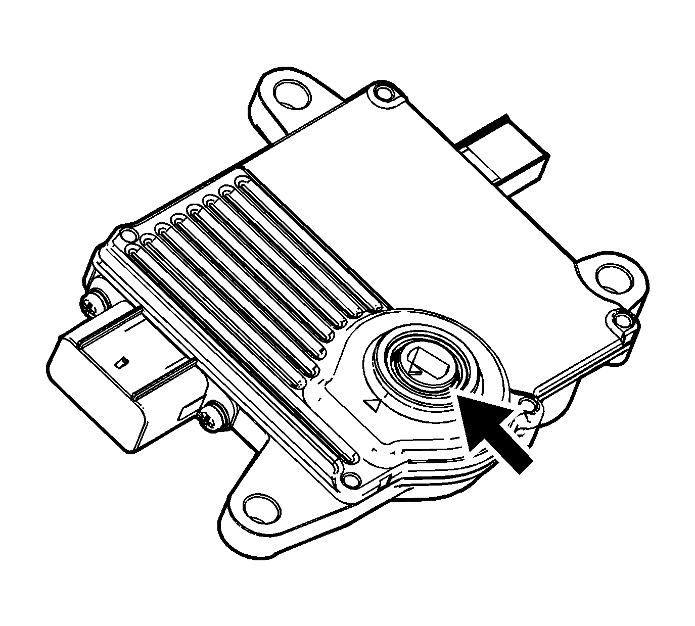
The transmission range (TR) switch is an integral part of the transmission control module (TCM). The TR switch input/output circuitry consists of supply voltage (Vcc), ground (GND), position signal 1 (Pos 1), and position signal 2 (Pos 2). Each gear range position (P, R, N, D, 4, 3, and 2) corresponds to a particular voltage (1-5 volts) within the TCM.
